Radiating unit and broadband high-intermodulation omni-directional ceiling antenna
A technology of radiation unit and ceiling antenna, applied in the field of wireless communication, can solve problems such as high cost and low intermodulation, and achieve the effects of low cost, high intermodulation requirements and simple processing
- Summary
- Abstract
- Description
- Claims
- Application Information
AI Technical Summary
Problems solved by technology
Method used
Image
Examples
Embodiment 1
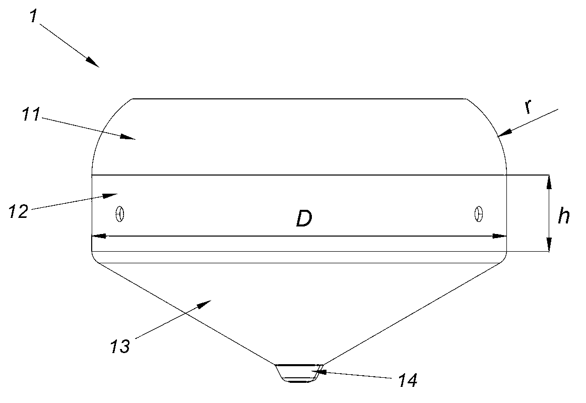
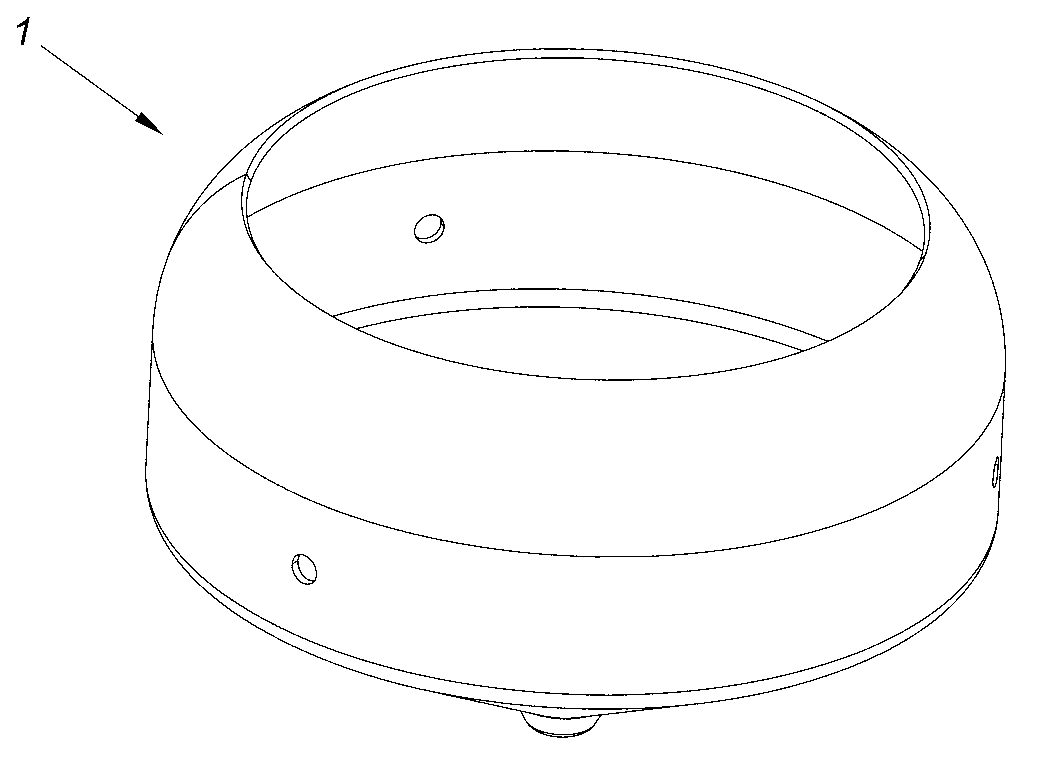
[0024] Such as figure 1 , figure 2 , image 3 As shown, the radiation unit 1 of this embodiment is a rotating casing integrally made of metal material. The rotating housing is sequentially composed of an arc portion 11 , a cylindrical portion 12 and a conical portion 13 . The taper of the conical part 13 is 4:1, and the diameter D of the bottom surface is 95 mm. The height h of the cylindrical portion 12 was 25 mm. The curvature radius r of the arc portion 11 is 21 mm.
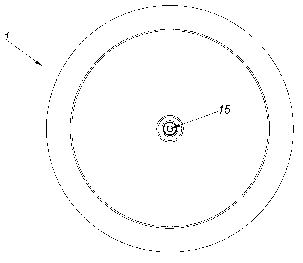
[0025] In this embodiment, at the top end of the conical portion 13, a connecting portion 14 protruding slightly outward is provided, such as figure 2 As shown, a connecting hole 15 is provided in the center of the connecting portion 14 for electrical conduction between the radiation unit 1 and the feeding connector.
Embodiment 2
[0027] Such as Figure 4 As shown, the broadband high intermodulation omnidirectional ceiling antenna of this embodiment includes: a housing 2 , a radiation unit 1 , a reflector 3 , a connection piece 4 and a feed connection piece 5 .
[0028] Wherein, the radiation unit 1 adopts the structure of the first embodiment. The top end of the conical portion 13 of the radiating unit 1 conducts with the inner conductor of the feeding connector 5 . One end of the connecting piece 4 is mechanically connected and conducted with the cylindrical portion 12 of the radiation unit 1 , and the other end of the connecting piece 4 is mechanically connected and conducted with the reflector 3 . Such as Figure 5 As shown, the distance d between the radiation unit 1 and the reflection plate 3 in this embodiment is 5mm.
[0029] The feed connector 5 of this embodiment is composed of a feed screw 51, a feed nut 52, a coaxial cable outer lead 53 and a coaxial cable connection terminal 54 connected...
Embodiment 3
[0031] The difference between this embodiment and Embodiment 2 lies in the structure of the feed connector. Such as Image 6 As shown, the feed connector of this embodiment includes: a connector body 6, the connector body 6 is made of metal, and a flange portion 61 and a coaxial connection portion 62 are arranged on the connector body 6; 6 is provided with an inner conductor 63, and there is an insulating layer 64 between the inner conductor 63 and the connector body 6; one end of the inner conductor 63 protrudes from the flange portion 61; Communicate with the outside world.
[0032] After being assembled on the reflector, the end of the inner conductor 63 protruding from the flange portion 61 will reach the top of the conical portion 13 of the radiating unit 1 , so that the inner conductor 63 can communicate with the radiating unit 1 .
[0033] Tests have shown that the electrical performance indicators of the broadband high-third-order intermodulation omnidirectional ceil...
PUM
 Abstract
Description
Claims
Application Information
 - R&D
- Intellectual Property
- Life Sciences
- Materials
- Tech Scout
- Unparalleled Data Quality
- Higher Quality Content
- 60% Fewer Hallucinations
Browse by: Latest US Patents, China's latest patents, Technical Efficacy Thesaurus, Application Domain, Technology Topic, Popular Technical Reports.
© 2025 PatSnap. All rights reserved.Legal|Privacy policy|Modern Slavery Act Transparency Statement|Sitemap|About US| Contact US: help@patsnap.com


