An air capacitor structure for matching equipment

A capacitor structure and matching technology, which is applied to multiple fixed capacitors, fixed capacitor components, and fixed capacitor terminals, etc. The service life of the equipment is not long, so as to achieve the effect of improving the reliability performance, improving the service life, and improving the ability to withstand current.

Active Publication Date: 2016-01-20
SOI MICRO CO LTD
View PDF3 Cites 0 Cited by
  • Summary
  • Abstract
  • Description
  • Claims
  • Application Information

AI Technical Summary

Problems solved by technology

Due to the power and load cavity, it is easy to cause the air capacitor connecting rod to burn black and burn out, and it is difficult to guarantee the reliability of the matching equipment, so that the service life of the matching equipment is not long

Method used


Image

  • An air capacitor structure for matching equipment
  • An air capacitor structure for matching equipment
  • An air capacitor structure for matching equipment

Examples


Embodiment Construction

[0020] The technical solution of the present invention will be described in detail below in conjunction with the accompanying drawings and embodiments.

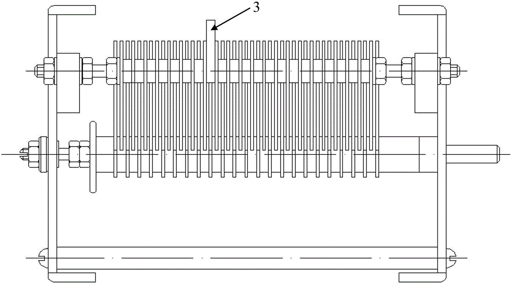
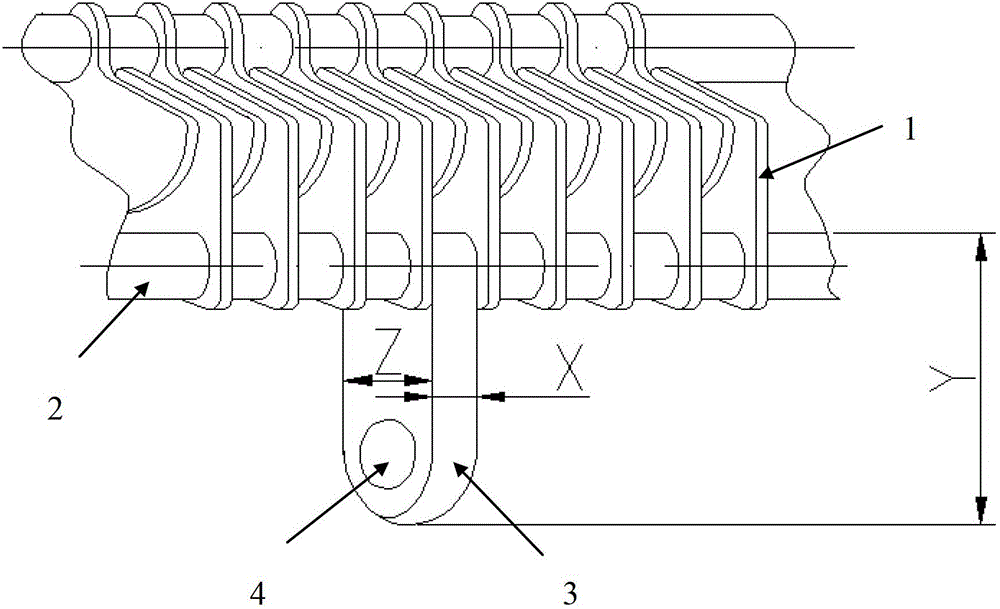
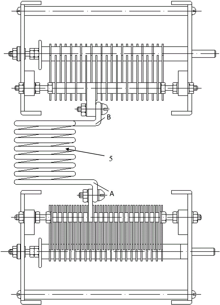
[0021] like figure 1 and figure 2 As shown, the embodiment of the present invention provides an air capacitor structure for a matching device, the air capacitor structure includes a fixed capacitor 1 and a connecting rod 2 connecting each capacitor 1, the connecting rod 2 is fixedly provided with a connection The rod 2 is connected to the column 3 with the same material. The connecting column 3 can be located at any position on the connecting rod 2 of the air capacitor structure except the two ends of the connecting rod 2, and is integrated with the connecting rod 2 of the air capacitor structure, and the material is pure aluminum. The connecting column 3 is provided with a circular screw through hole 4 for connecting with the silver-plated coil. The silver-plated coil is fixed on the through hole 4 by bolts. The diameter ...


PUM


Abstract

The invention relates to the technical field of plasma etching and depositing equipment and specifically relates to an air capacitor structure for matcher equipment. The air capacitor structure comprises a capacitor piece and a connecting rod connected with the capacitor piece; a connecting column is fixedly arranged on the connecting rod; and a silver jacketed coil is connected with the connecting rod by the connecting column. Through arranging the connecting column on the connecting rod of the air capacitor, the heavy current running through the air capacitor in a plasma technology is distributed evenly, thus the current resistance of the capacitor is favorably improved, the capacity range of the capacitor is improved, the service life of the air capacitor is improved directly, the reliability of the matching property is enhanced and the service life of the total equipment is prolonged.

Description

technical field [0001] The invention relates to the technical field of plasma etching and deposition equipment, in particular to an air capacitor structure used for matching equipment. Background technique [0002] In plasma processes such as etching and deposition, a matching device is required. The air capacitor in the matching device is connected to the silver-plated coil in such a way that one end of the silver-plated coil is directly connected to the end of the air capacitor connecting rod. Due to the power and load cavity, it is easy to cause the connecting rod of the air capacitor to burn black and burn out, and it is difficult to guarantee the reliability of the matching equipment, so that the service life of the matching equipment is not long. Contents of the invention [0003] The purpose of the present invention is to provide an air capacitor structure for matching equipment, which can realize the uniform distribution of large current passing through the air cap...

Claims


Application Information

Patent Timeline
Patent Type & Authority Patents(China)
IPC IPC(8): H01G4/228H01G4/38
Inventor 杨进徐维江李勇滔夏洋
Owner SOI MICRO CO LTD
Why Eureka
Try Eureka