Eureka AIR delivers breakthrough ideas for toughest innovation challenges, trusted by R&D personnel around the world.

Integrated long-focus measuring device based on Talbot-moire technology

A measurement device and a long focal length technology, which is applied in the direction of testing optical performance, etc., can solve the problems of complex optical system measurement environment, complex measurement process, inconvenient on-site measurement, etc., to achieve simple measurement process, improve measurement accuracy, and ensure consistency.

Inactive Publication Date: 2013-04-24
NANJING UNIV OF SCI & TECH +1
View PDF6 Cites 7 Cited by
  • Summary
  • Abstract
  • Description
  • Claims
  • Application Information

AI Technical Summary

Problems solved by technology

Traditional measurement methods are convenient and highly accurate when measuring optical components with small focal lengths, but for long focal length optical components, these methods require complex optical systems and strict measurement environments
Measuring length and focal length based on Talbot-Moiré fringe technology is a relatively high-precision measurement method. The light source system, Talbot interferometer and image acquisition system in the measurement device of this method usually adopt a split structure, which is not convenient for on-site measurement. ; Some measuring devices integrate the light source system and the Taber interferometer, but there is no point-to-point device, which makes the measurement process more complicated, cumbersome to operate, and not easy to carry

Method used


Image

  • Integrated long-focus measuring device based on Talbot-moire technology
  • Integrated long-focus measuring device based on Talbot-moire technology
  • Integrated long-focus measuring device based on Talbot-moire technology

Examples


Embodiment Construction

[0021] The present invention will be further described below in conjunction with the drawings and specific embodiments.

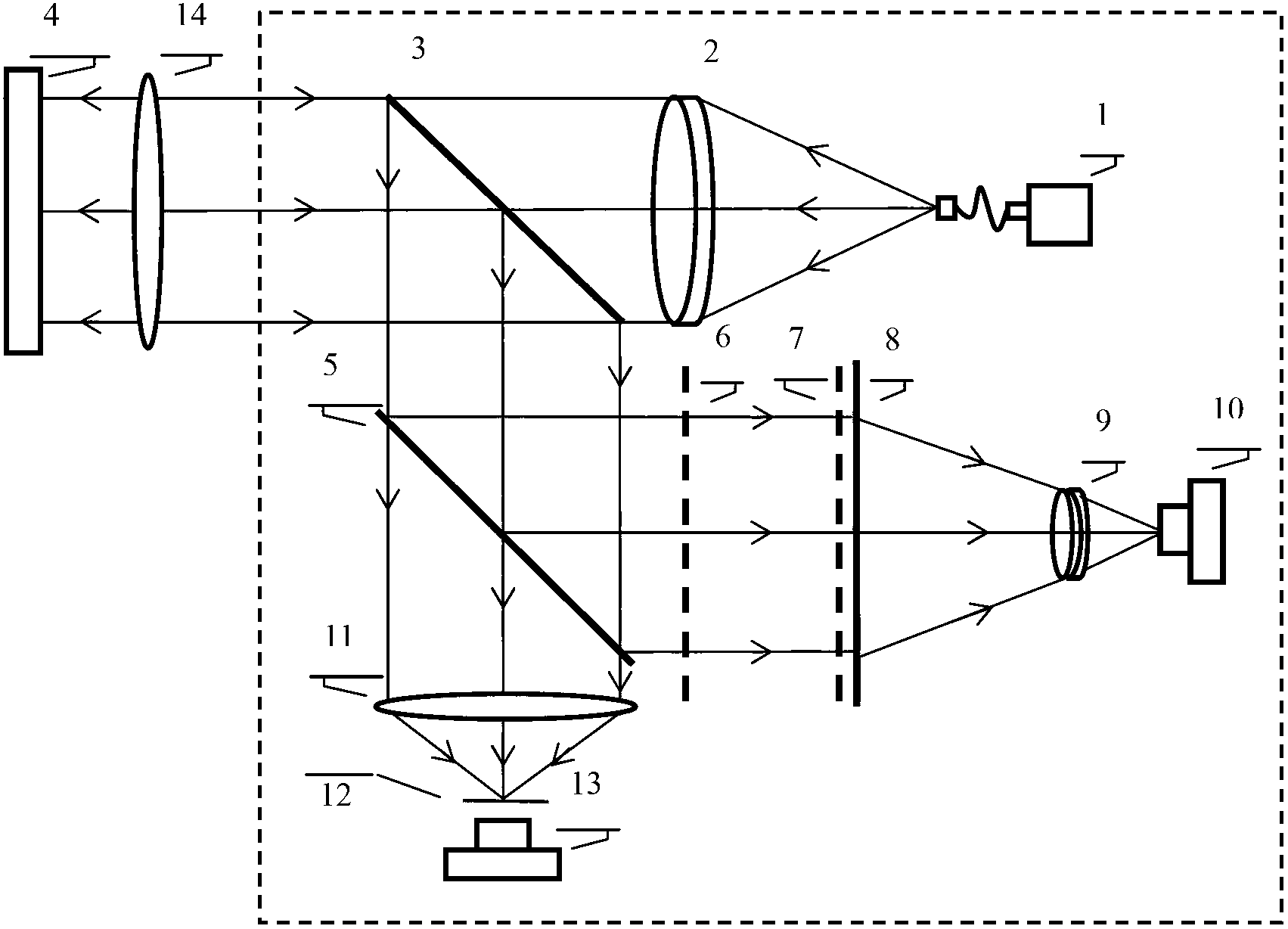
[0022] Combine figure 1 , The present invention is an integrated long focal length measuring device based on Taber-Moiré fringe technology, including a laser 1, an aspherical collimating objective lens 2, an antireflection lens 3, a plane mirror 4, a half mirror 5, The first grating 6, the second grating 7, the first scattering plate 8, the imaging lens 9, the first CCD 10, the condensing lens 11, the second scattering plate 12, the second CCD 13, and the long focal length lens 14 to be measured; the light emitted by the laser 1 After passing through the aspherical collimating objective lens 2, a collimated laser beam is formed, which is incident on the side of the anti-reflection lens 3 on which the anti-reflection lens 3 is coated with the anti-reflection coating and is completely transmitted. The transmitted light passes through the long focal length lens 14...


PUM


Abstract

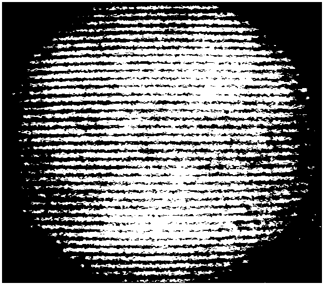
The invention discloses an integrated long-focus measuring device based on Talbot-moire technology. The integrated long-focus measuring device based on the Talbot-moire technology comprises a laser device, an aspheric surface collimator lens, a one-side anti-reflection one-side increase-reflection lens, a plane mirror, a semi-reflection and semi-anti-reflection mirror, a Talbot interferometer, an imaging lens, a first charge coupled device (CCD), a counter point system and a long-focus lens to be measured. The Talbot interferometer comprises first optical grating, a second optical grating and a first scatter plate. The counter point system comprises a convergent lens, a second scatter plate and a second CCD. When the long-focus lens to be measured is not placed to the device, system optical axes are adjusted into consistency by utilizing the counter point system. Then a moire fringe L1 collected by the first CCD is input to a computer. The moire fringe L1 is placed into the long-focus lens to be measured. A moire fringe L2 including focal distance collected by the first CCD is input to the computer together with the moire fringe L1. An included angle formed by the moire fringe L1 and the moire fringe L2 is calculated through the computer to obtain a focal length f of the lens to be measured. The counter point system is designed in the device, the consistency of the axes of the system is ensured, and long-focus measurement with high precision can be achieved.

Description

Technical field [0001] The invention relates to the field of focal length measurement of optical elements and optical systems, in particular to an integrated long focal length measurement device based on Taber-Mohr technology. Background technique [0002] At present, there are two main methods for measuring the focal length of long focal length optical elements and optical systems: the traditional measurement method and the Taber-Moiré fringe method. Traditional measurement methods are convenient and highly accurate when measuring optical elements with small focal lengths, but for long focal length optical elements, these methods require complex optical systems and strict measurement environments. Measuring the focal length based on the Taber-Moiré fringe technique is a highly accurate measurement method. The light source system, Taber interferometer and image acquisition system in the measuring device of this method usually adopt a split structure, which is not convenient for o...

Claims


Application Information

Patent Timeline
Patent Type & Authority Applications(China)
IPC IPC(8): G01M11/02
Inventor 李建欣何勇陈好陆衡赵琦樊红英蒋泽伟朱日宏陈磊高志山王青郭仁慧沈华马骏
Owner NANJING UNIV OF SCI & TECH
Why Eureka
Eureka Blog
Learn More