
Driving and suspension integrated multi-phase fly wheel energy storage device

A flywheel energy storage and integrated technology, which is applied in the field of flywheel energy storage, can solve the problems of difficult to achieve high-reliability suspension and rotation coordination control, increase the difficulty of control and realization, and it is not easy to insert wires and manufacture, etc. Bearing control components, low power consumption, easy to embedding effect

Active Publication Date: 2013-04-17
ZHEJIANG UNIV
View PDF4 Cites 17 Cited by
  • Summary
  • Abstract
  • Description
  • Claims
  • Application Information

AI Technical Summary

Problems solved by technology

Since the stator needs two sets of windings, the structure of the motor is relatively complex, it is not easy to insert wires and manufacture, and the power loss on the stator side is relatively large; the power level of the inverter used for torque winding control and the inverter used for suspension winding control Different, under the condition of large load disturbance and high-speed rotation, it is difficult to realize the coordinated control between suspension and rotation with high reliability; the electromagnetic coupling between the two sets of windings also greatly increases the difficulty of control and implementation

Method used


Image

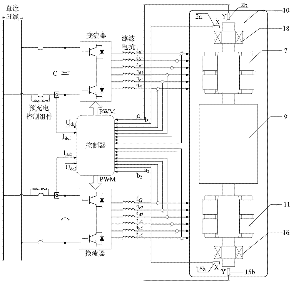
  • Driving and suspension integrated multi-phase fly wheel energy storage device
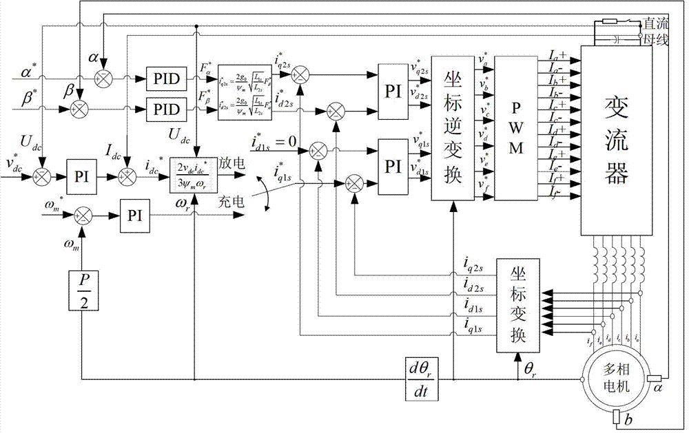
  • Driving and suspension integrated multi-phase fly wheel energy storage device
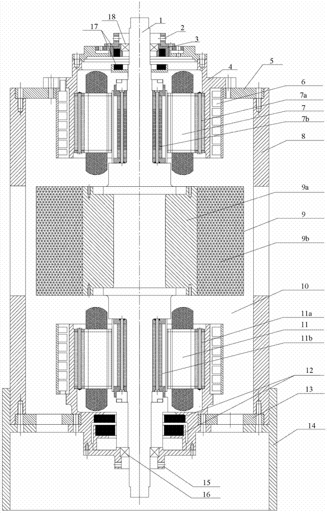
  • Driving and suspension integrated multi-phase fly wheel energy storage device

Examples


Embodiment Construction

[0036] In order to describe the present invention more specifically, the technical solutions and related working principles of the present invention will be described in detail below in conjunction with the accompanying drawings and specific embodiments.

[0037] Such as figure 1 and 2As shown, a multi-phase flywheel energy storage device integrating drive and suspension, including: casing, main shaft 1, converter and controller; main shaft 1 is set in the casing, and the upper, middle and lower parts of main shaft 1 are installed respectively There is a first polyphase motor 7 , a flywheel 9 and a second polyphase motor 11 .

[0038] The casing includes a base 14, a lower bracket 13, an outer bracket 8 and an upper bracket 4; the lower bracket 13 is arranged on the base 14, and the upper bracket 4 is connected with the lower bracket 13 through the outer bracket 8; the inside of the housing needs to be evacuated to form a flywheel Vacuum chamber 10.

[0039] The flywheel 9 ...


PUM


Abstract

The invention discloses a driving and suspension integrated multi-phase fly wheel energy storage device, which comprises a shell, a main shaft, a current transformer and a controller, wherein the upper, middle and lower parts of the main shaft are provided with a first multi-phase motor, a fly wheel and a second multi-phase motor respectively; each multi-phase motor comprises a rotor and a stator; each stator is provided with n phases of windings; each phase of winding is a distributed winding and is asymmetrically distributed along the circumference of an air gap; and the current transformer is an n-phase current transformer. According to the driving and suspension integrated multi-phase fly wheel energy storage device, fly wheel energy storage, and driving and magnetic suspension functions of the multi-phase motors are integrated into a whole; radial magnetic bearing components at two ends of the main shaft are reduced, so that extra axial space is not occupied; the system has a simpler and more compact structure; the bearing rigidity and the space utilization rate are greatly improved; and the driving and suspension integrated multi-phase fly wheel energy storage device has broad application and development prospect in the high-speed fly wheel energy storage system of high energy storage density, high transformation efficiency, low idle speed loss and long service life.

Description

technical field [0001] The invention belongs to the technical field of flywheel energy storage, and in particular relates to a multiphase flywheel energy storage device integrating drive and suspension. Background technique [0002] Flywheel energy storage technology uses a high-speed rotating flywheel as a carrier, converts electrical energy into mechanical energy and stores it in the high-speed rotating flywheel, and realizes the storage and release of electric energy by increasing and decreasing the speed of the flywheel and the motor. With the emergence and development of high-strength composite carbon fiber materials, magnetic suspension bearing technology and high-performance power contactor devices, flywheel energy storage is characterized by its stability, high efficiency, environmental protection, long life, high energy storage density, and is not limited by the number of charge and discharge. It has a wide range of applications in the fields of power system peak re...

Claims


Application Information

Patent Timeline
IPC IPC(8): H02K7/02
CPCY02E60/16
Inventor 杨家强黄进曾争许加凯高健俞年昌
Owner ZHEJIANG UNIV
Learn More