Interlocking device of change-over switch

A technology of transfer switch and interlocking device

Active Publication Date: 2013-04-17
SEARI ELECTRIC TECH +1
View PDF6 Cites 8 Cited by
  • Summary
  • Abstract
  • Description
  • Claims
  • Application Information

AI Technical Summary

Problems solved by technology

[0006] The operating mechanisms disclosed in the above two patent applications are suitable for small-scale manual operation, but for large-capacity transfer switch appliances, the above-mentioned operating mechanisms are not suitable

Method used


Image

  • Interlocking device of change-over switch
  • Interlocking device of change-over switch
  • Interlocking device of change-over switch

Examples


Embodiment Construction

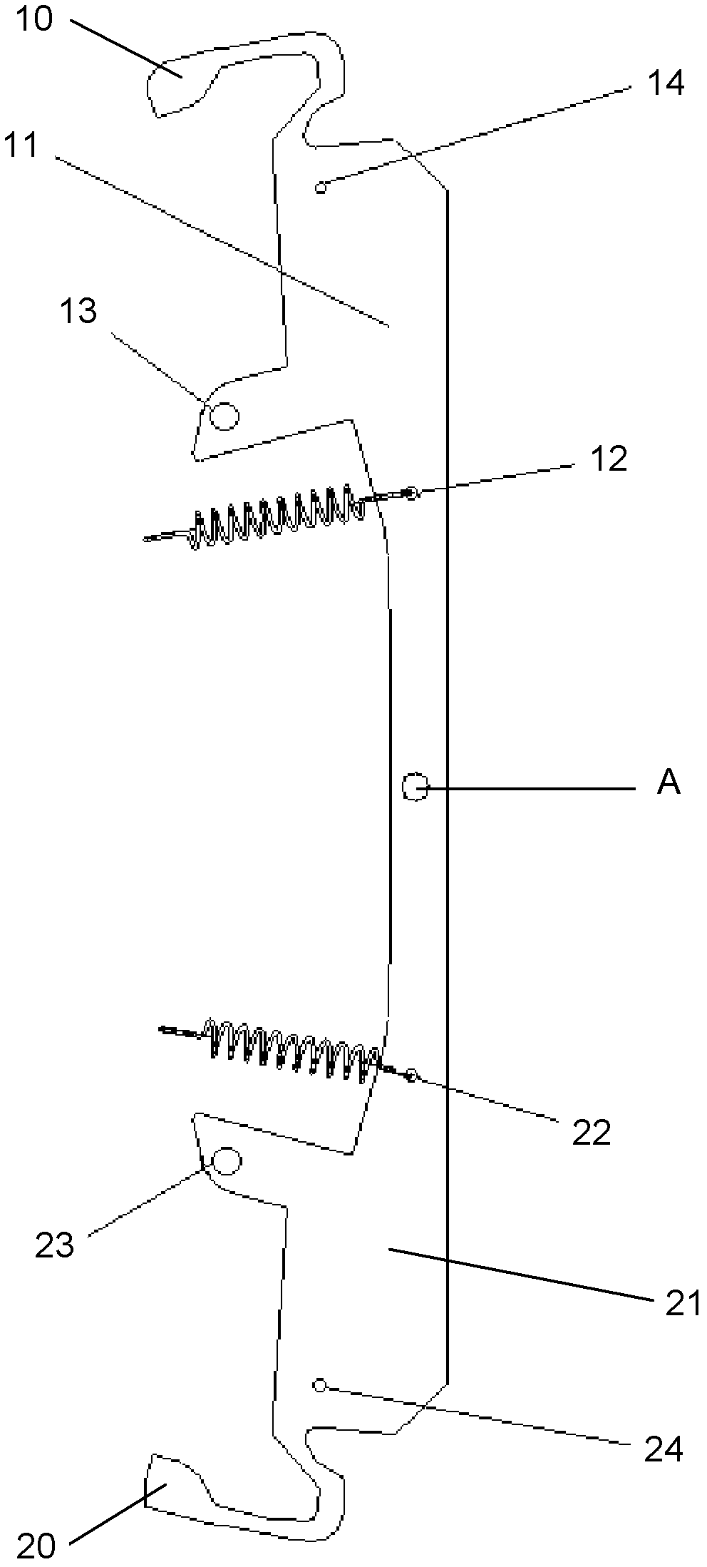
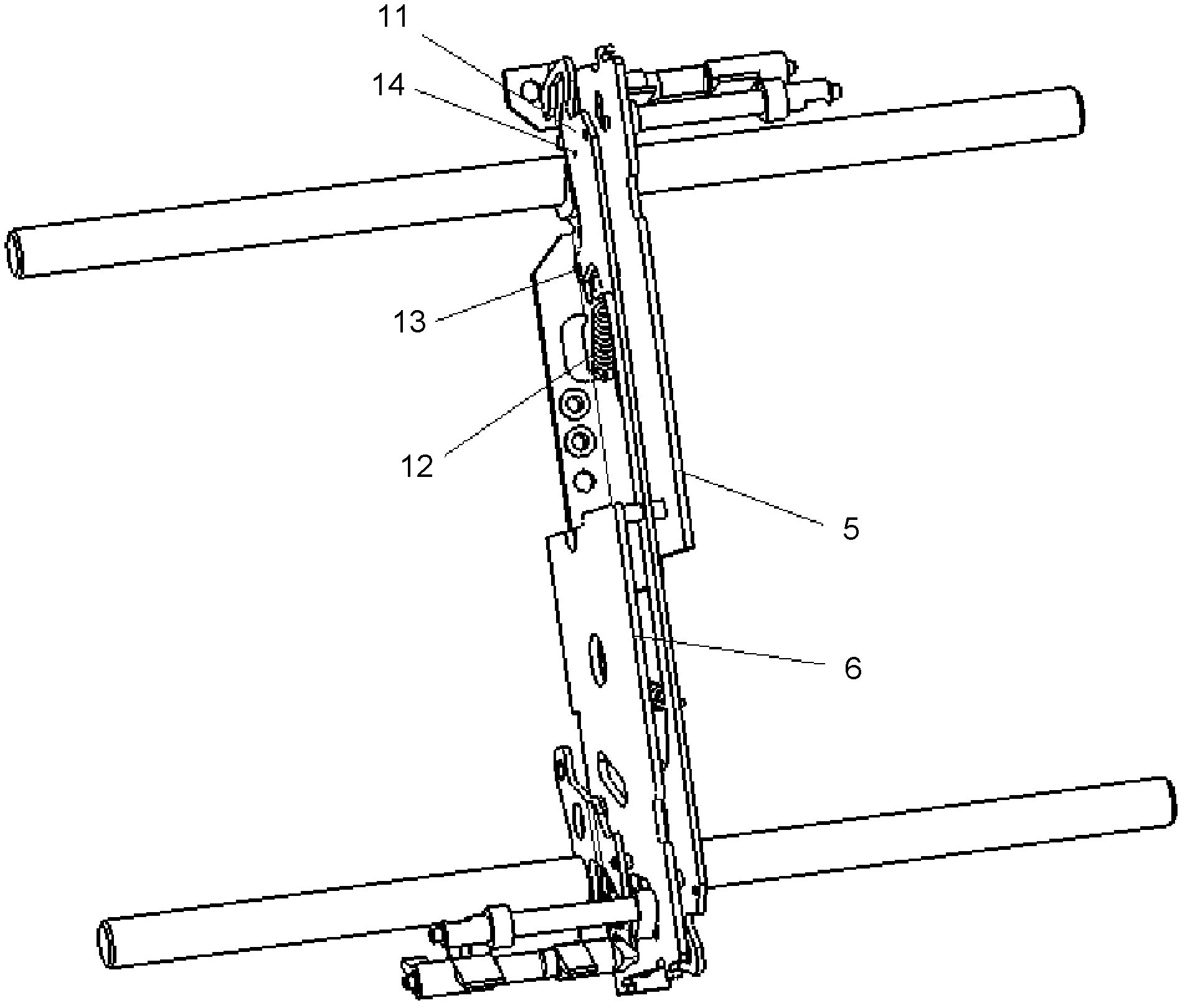
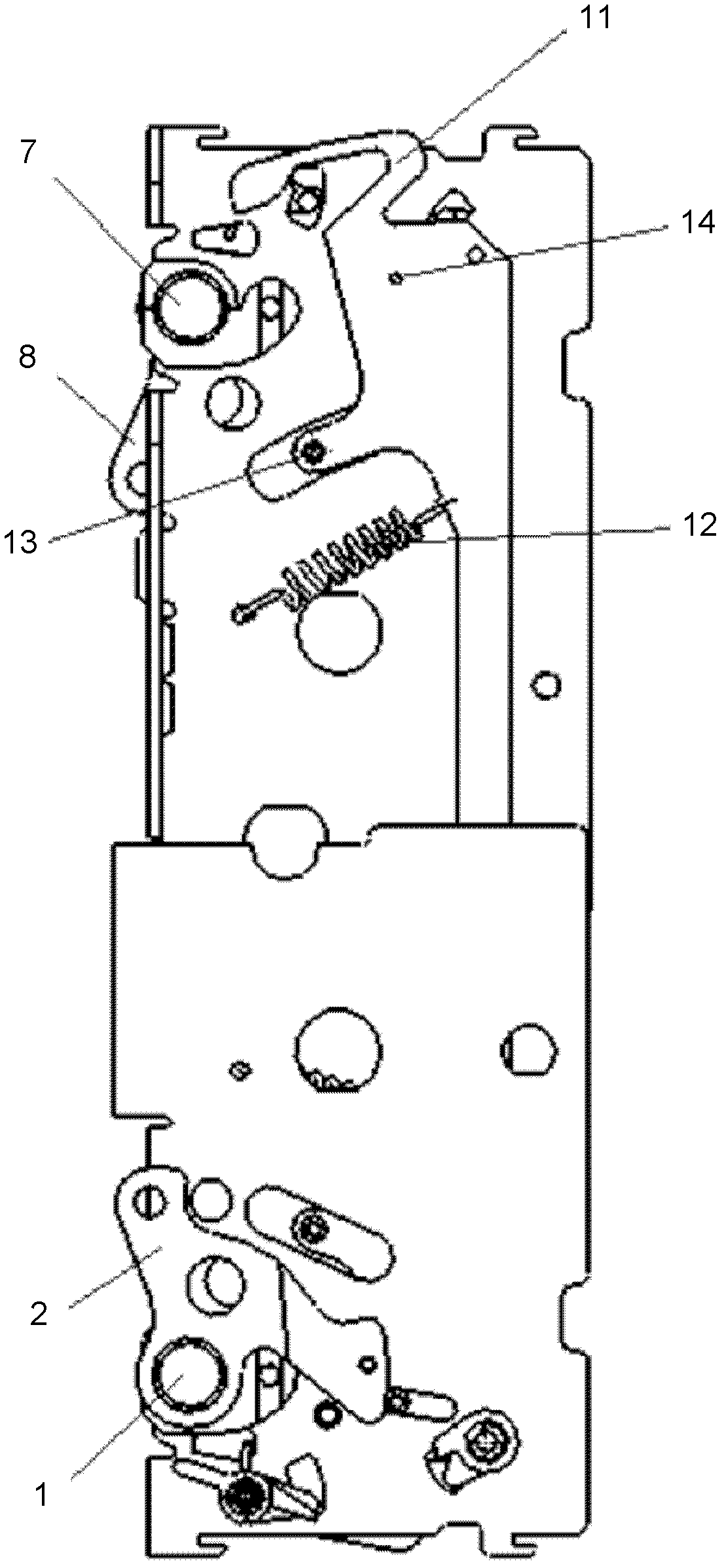
[0028] refer to Figure 1-Figure 8 As shown, the present invention discloses an interlock device of a transfer switch, wherein figure 1 reveals the structure of the interlock, Figure 2-Figure 8 It is disclosed that the interlocking device is installed on the operating mechanism of the transfer switch and that the transfer switch is in different working states.

[0029] The interlocking device of the transfer switch includes an upper part and a lower part with symmetrical structures, and the interlocking device is installed at the middle gap of the operating mechanism of the transfer switch. In the illustrated embodiment, the interlocking device is installed symmetrically and crosswise at the middle gap of the operating mechanism of the transfer switch.

[0030] The upper part comprises an upper interlocking rod 11, an upper limit pin 14 positioned at the end of the upper interlocking rod 11, an upper return spring 12 fixed on the upper interlocking rod 11, and an upper retu...


PUM


Abstract

The invention discloses an interlocking device of a change-over switch. The interlocking device of the change-over switch comprises an upper part and a lower part, which are in a symmetrical structure. The interlocking device is mounted at the position of a middle interval of an operation mechanism of the change-over switch; each one of the upper part and the lower part comprises an interlocking rod, a limiting pin located at the end part of the interlocking rod, a resetting spring with one end fixed with the interlocking rod, and an idler wheel located between the limiting pin and the resetting spring; and the end part of each interlocking rod extends out to form an arch upper protruding part. A spindle at one of the upper part and the lower part of the operation mechanism drives a cantilever to rotate; each interlocking rod is pushed to rotate around a rotating point in a rotating process; and the protruding part on each interlocking rod presses a tripping rod at the other part of the operation mechanism, so that the tripping rod is prevented from moving. Therefore, conversion between a power source at a normal side and a power source at a spare side is realized. The interlocking device of the change-over switch provided by the invention has the advantages of simple structure, high security and high reliability, no occupied space, small size, easiness of realization and low cost, and is mounted and works by fully using an own interval.

Description

technical field [0001] The invention relates to the field of low-voltage electrical appliances, and more specifically relates to an interlock device for a transfer switch. Background technique [0002] The transfer switch equipment (TSE) is mainly used for the switching of two circuits, and the simultaneous closing of the two sets of contacts is not allowed during the switching process. The transfer switching device TSE is widely used in the power supply flow of two power sources, such as emergency power supply flow, fire power supply flow, and power supply flow that does not allow long-term power failure, and can also be used as a switch between two loads. [0003] Most of the existing transfer switch appliances use shift fork technology, which is mainly used in small-capacity transfer switch appliances. so that the other side cannot be closed. [0004] For example, the application number is CN200710070222.0, and the patent application titled "a mechanical interlocking de...

Claims


Application Information

Patent Timeline
Patent Type & Authority Applications(China)
IPC IPC(8): H01H9/26
Inventor 周密曲德刚弓海深李甲蒋凯
Owner SEARI ELECTRIC TECH
Why Eureka
Try Eureka