


Quick Research
Generate reliable direction feasibility study reports for your R&D in just a few steps.

Technical Q&A
Discover and master advanced knowledge NOW. Basics, ideas, possibilities, all at once.

Find Solutions
As an expert in R&D theories, this can generate solutions to your technical problems instantly.

Evaluate Feasibility
Analyze your overall solution with one click, know your potential R&D risks in advance.

Monitor Landscape
Get weekly tech updates, stay abreast of the latest tech innovations and key insights.
High-voltage electrifying display device
A high-voltage charged display and capacitance technology, which is applied in the direction of measuring devices, measuring electrical variables, and measuring current/voltage, can solve problems such as potential safety hazards, low induction current, and weak flickering intensity of flash components, so as to ensure work safety and flickering intensity Strengthen and eliminate potential safety hazards
- Summary
- Abstract
- Description
- Claims
- Application Information
AI Technical Summary
Problems solved by technology
Method used
Image

Examples
Embodiment
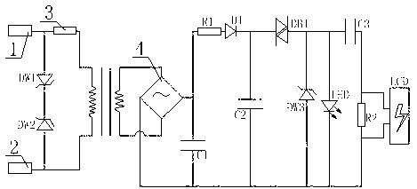
[0023] Such as figure 1As shown, the high-voltage charged display device includes a casing and an internal circuit structure arranged in the casing, wherein the internal circuit structure includes a high-impedance attenuator, a magnetic core transformer, a rectifier, a charge-discharge oscillator, and a flash component connected in sequence. The magnetic core transformer has a primary side connected to the high-impedance attenuator and a secondary side connected to the rectifier. Both the primary side and the secondary side of the magnetic core transformer are equipped with coils, and the number of coil turns on the primary side of the magnetic core transformer is greater than that of the secondary side. The number of turns of the side coil. The rectifier includes a rectifier unit 4, a first capacitor C1, a first rectifier diode D1 and a first resistor R1, wherein the rectifier unit 4 preferably adopts a bridge rectifier circuit, the first resistor R1, the first rectifier diod...
Embodiment 2
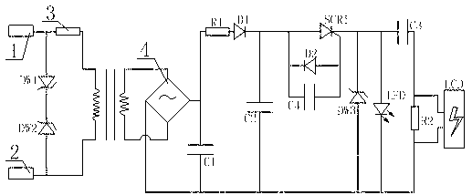
[0027] Such as figure 2 As shown, the difference between this embodiment and Embodiment 1 is that the charging and discharging oscillator is different. The charging and discharging oscillator in this embodiment includes a second capacitor C2 and a voltage-type trigger circuit. The capacitor C2 is connected in parallel, and the voltage-type trigger circuit includes a fourth capacitor C4, a first unidirectional thyristor SCR1, and a reversely connected second trigger diode D2, after the fourth capacitor C4 is connected in parallel with the reversely connected second trigger diode D2, and then It is connected in parallel with the input pin and the control pin of the first one-way thyristor SCR1.
Embodiment 3
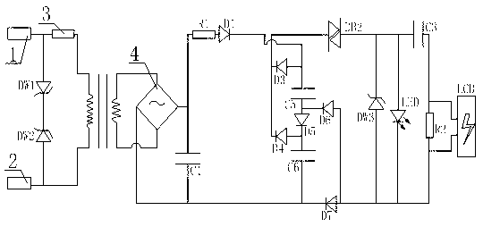
[0029] Such as image 3 As shown, the difference between this embodiment and Embodiment 1 is that the charge and discharge oscillator is replaced. The charge and discharge oscillator in this embodiment includes a fifth capacitor C5, a sixth capacitor C6, a third diode D3, a fourth The diode D4, the fifth diode D5, the sixth diode D6, the seventh diode D7 and the second bidirectional switch diode DB2, wherein the second bidirectional switch diode DB2 is connected in series with the flash unit, and the fifth capacitor C5, the fifth diode D5 and the sixth capacitor C6 are sequentially connected in series to form a series branch connected to the rectifier, and the anodes of the third diode D3 and the fourth diode D4 are respectively connected to the fifth capacitor C5 and The anode of the sixth capacitor C6 is connected, the cathodes of both the third diode D3 and the fourth diode D4 are connected to the input end of the second bidirectional switch diode DB2, the sixth diode D6 an...
PUM
 Abstract
Description
Claims
Application Information
 - R&D Engineer
- R&D Manager
- IP Professional
- Industry Leading Data Capabilities
- Powerful AI technology
- Patent DNA Extraction
Browse by: Latest US Patents, China's latest patents, Technical Efficacy Thesaurus, Application Domain, Technology Topic, Popular Technical Reports.
© 2024 PatSnap. All rights reserved.Legal|Privacy policy|Modern Slavery Act Transparency Statement|Sitemap|About US| Contact US: help@patsnap.com