Clamping device and levelling method for slice carrying table of ultrasonic scanning microscope

A technology of ultrasonic scanning and clamping device, which is used in measuring devices, material analysis using sonic/ultrasonic/infrasonic waves, instruments, etc. It can solve the problem of corrosion and rust of parts and fastening screws, loss of reliability, loss of operational flexibility and other problems to achieve the effect of preventing parts from rusting, simple operation and easy leveling

Inactive Publication Date: 2013-04-17
THE 45TH RES INST OF CETC
View PDF6 Cites 3 Cited by
  • Summary
  • Abstract
  • Description
  • Claims
  • Application Information

AI Technical Summary

Problems solved by technology

This kind of structure, firstly, it is very inconvenient to replace or pick and place the film carrier in real time; secondly, only one of the film carrier or the standard material box can be fixed and installed on the support frame, and cannot be replaced in real time. Therefore, the standard material box can only be placed on the film support table, and an additional fixing device is added to fix the standard material box
In addition, because the connections between the supporting frame members are usually fastened by screws, and the main support members of the wafer table and the frame on the frame are all working in a pure water medium environment, so the related parts and fastening screws are very easy to produce Corrosion and rust make the conventional support frame of the film table not only lose the flexibility of operation, but also lose the reliability of use

Method used


Image

  • Clamping device and levelling method for slice carrying table of ultrasonic scanning microscope
  • Clamping device and levelling method for slice carrying table of ultrasonic scanning microscope
  • Clamping device and levelling method for slice carrying table of ultrasonic scanning microscope

Examples


Embodiment Construction

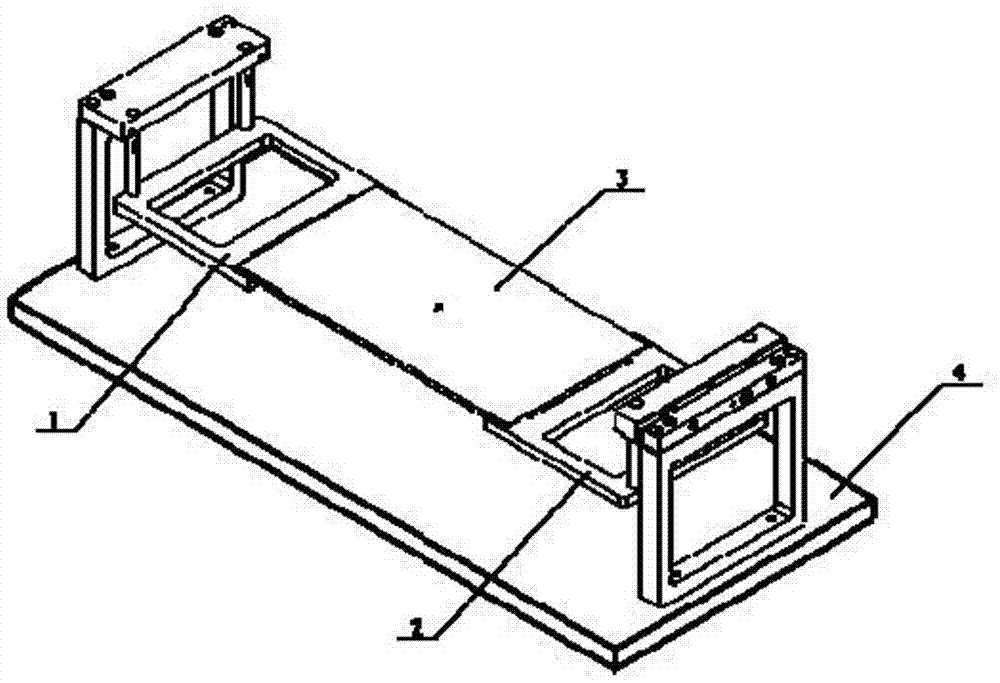
[0028] Such as figure 1 , Figure 8 As shown, the wafer stage clamping device of the ultrasonic scanning microscope of the present invention includes a base 4 and the wafer stage 3 or a standard magazine 24, and the wafer stage clamping device of the ultrasonic scanning microscope of the present invention is characterized in that: the base 4 A fixed bracket structure 1 and a movable bracket structure 2 are respectively fixed at both ends of the bracket, the fixed bracket structure 1 and the movable bracket structure 2 hold and clamp the wafer stage 3 or Standard cartridge 24.

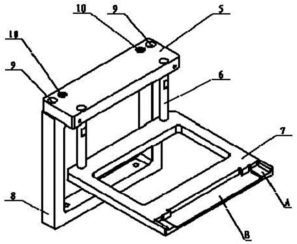
[0029] Such as figure 2 As shown, the fixed bracket structure 1 is composed of a left column 8, a left upper seat 5, a left column 6 and a left bracket 7. The bottom end of the left column 8 is fixed on the base 4 by screws, and the upper end is fixed by two The locking screw 9 and the two adjustment screws 10 are connected to the outside of the left upper seat 5, and the inner two ends of the left ...


PUM


Abstract

The invention provides a clamping device for a slice carrying table of an ultrasonic scanning microscope, which comprises a base and a slice carrying table or a standard feed box. A fixed carrier structure and a movable carrier structure are fixed at the two ends of the base respectively, a supporting plane of slice carrying table and a supporting plane of standard feed box are arranged on the carriers of the two structures respectively, and the slice carrying table or the standard feed box is supported and clamped between the two structures. The movable carrier structure is provided with a guide device, a reset device and a limiting device. The right carrier has a manual clamp motion path by virtue of the guide device, the reset device and the limiting device. Left and right upright columns working in a water medium and the left and the right carriers are all made of PMMA, so as to eliminate the risk of rust formation of parts and connecting bolts and avoid operation failure caused by rust corrosion of the device. The clamping device has a split structure, and the slice carrying table can be put in or taken out and clamped and fixed at any time and can be freely replaced by the standard feed box. The clamping device is easy to operate and provides convenience for leveling the slice carrying table under the ultrasonic scanning microscope.

Description

technical field [0001] The invention relates to an ultrasonic scanning detection device, in particular to a clamping device and a leveling method for a substrate table of an ultrasonic scanning microscope. Background technique [0002] A conventional support structure for a scanning ultrasound microscope stage is a monolithic frame structure assembled from structural members. On the frame, the parts of the supporting frame and between the parts and the wafer platform are all fixed by screw connections. This kind of structure, firstly, it is very inconvenient to replace or pick and place the film carrier in real time; secondly, only one of the film carrier or the standard material box can be fixed and installed on the support frame, and cannot be replaced in real time. Therefore, the standard material box can only be placed on the film support table, and an additional fixing device is added to fix the standard material box. In addition, because the connections between the s...

Claims


Application Information

Patent Timeline
Patent Type & Authority Applications(China)
IPC IPC(8): G01N29/22G01N29/26
Inventor 陶利权黄晓鹏付纯鹤张继静
Owner THE 45TH RES INST OF CETC
Why Eureka
Try Eureka