
Swinging spout for furnace

A technology of swinging nozzle and blast furnace, applied in the direction of discharge device, etc., can solve the problems of shortening the service life of the tank body, rapid loss of refractory materials, unstable transmission, etc., and achieves the effect of long service life, prolonging service life, and stable and reliable transmission.

Inactive Publication Date: 2013-04-17
MCC CAPITAL ENGINEERING & RESEARCH
View PDF5 Cites 6 Cited by
  • Summary
  • Abstract
  • Description
  • Claims
  • Application Information

AI Technical Summary

Problems solved by technology

[0003] In the swing nozzle in the prior art, the left and right tilting of the trough is manually driven, which not only wastes manpower, but also has low efficiency and unstable transmission
In addition, during the working process of the swing nozzle, the molten iron in the molten iron ditch will continuously flow into the groove body of the swing nozzle. Since the molten iron only impacts on one side of the groove body of the swing nozzle, this leads to long-term damage to the impacted side. The refractory material on the side wall of the tank body wears out quickly, which shortens the service life of the tank body

Method used


Image

  • Swinging spout for furnace
  • Swinging spout for furnace
  • Swinging spout for furnace

Examples


Embodiment Construction

[0025] The following will clearly and completely describe the technical solutions in the embodiments of the present invention with reference to the accompanying drawings in the embodiments of the present invention. Obviously, the described embodiments are only some, not all, embodiments of the present invention. Based on the embodiments of the present invention, all other embodiments obtained by persons of ordinary skill in the art without creative efforts fall within the protection scope of the present invention.

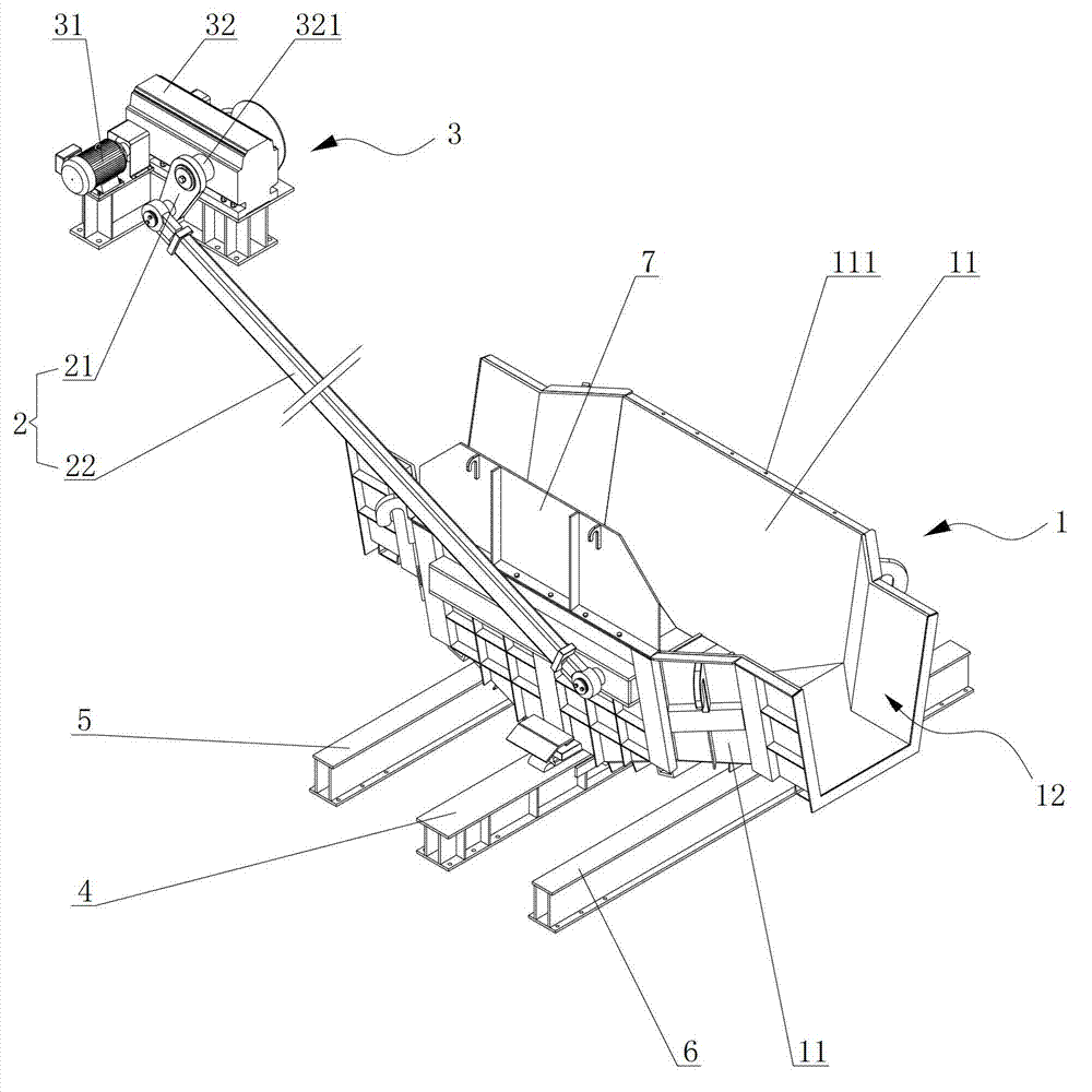
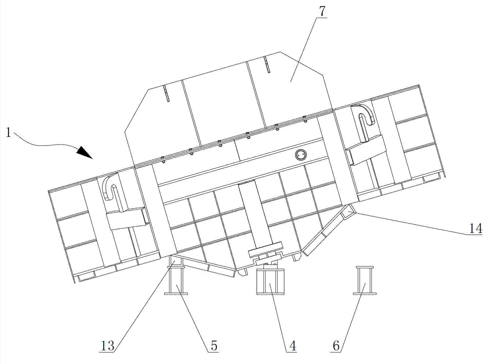
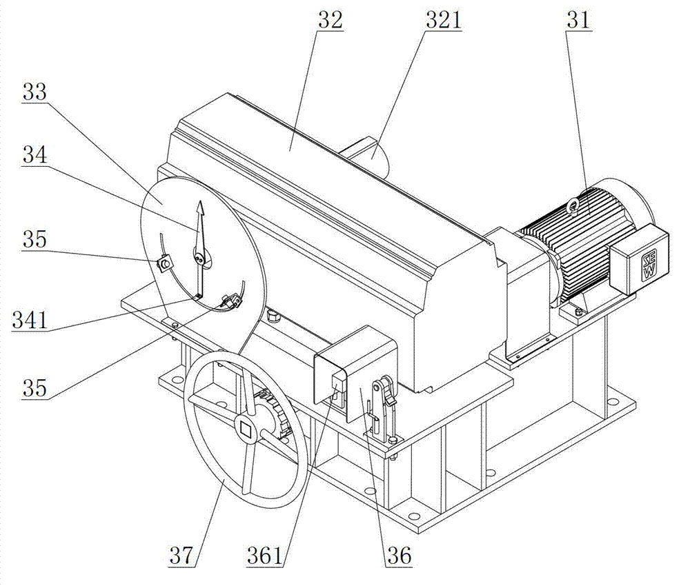
[0026] Such as figure 1 As shown, the present invention provides a swing nozzle for a blast furnace, which includes a tank body 1 , a connecting rod mechanism 2 and a driving device 3 . Wherein: the lower end of the tank body 1 is provided with a load-bearing beam 4, and the tank body 1 swings left and right along the load-bearing beam 4; the linkage mechanism 2 has a crank 21 and a long connecting rod 22, and one end of the long connecting rod 22 is rotatable gro...


PUM


Abstract

The invention discloses a swinging spout for a furnace. The swinging spout comprises a tank body, a link mechanism and a driving device, wherein a load-bearing beam is arranged at the lower end of the tank body; the tank body performs side-to-side swing along the tank body; the link mechanism consists of a crank and a long connecting rod; one end of the long connecting rod is rotatably connected to one end of the crank, and the other end is rotatably connected to the tank body; the driving device consists of a motor and a speed reducer, which are connected with each other; and an output shaft of the speed reducer is connected to the other end of the crank. According to the swinging spout for the furnace provided by the invention, the tank body can smoothly switch between the two-side operating positions of the load-bearing beam under the driving of the link mechanism, so that the transmission efficiency is high and the transmission is stable and reliable.

Description

technical field [0001] The present invention relates to a oscillating nozzle, in particular to a oscillating nozzle used in a blast furnace for transporting molten iron. Background technique [0002] For large-scale blast furnaces, due to the increase in the amount of iron tapping, the number of molten iron tanks increases, and the use of swing nozzles can shorten the length of the iron trench, simplify the layout of the casthouse, reduce the area of ​​the casthouse, improve operating conditions, and reduce labor intensity. The swing nozzle is set at the end of the iron ditch of the blast furnace casthouse and installed under the iron ditch of the casthouse. The molten iron flowing out of the iron ditch can be transferred to any direction on both sides of the iron ditch through the swing nozzle, so that the molten iron can be injected out smoothly. In the mixed iron car or molten iron tank car under the platform of the iron yard, after one molten iron tank is filled with mol...

Claims


Application Information

Patent Timeline
Patent Type & Authority Applications(China)
IPC IPC(8): C21B7/14
Inventor 王得刚姜凤山尚志升全强赵利明于丹
Owner MCC CAPITAL ENGINEERING & RESEARCH
Learn More