
Clamping fixture

A fixture and the same technology, applied in the field of fixtures, can solve the problems of low work efficiency, complicated processing technology, time-consuming and money-consuming, etc., and achieve good clamping effect

Inactive Publication Date: 2013-04-17
KUSN MAIZHI FIXTURE TECH
View PDF6 Cites 0 Cited by
  • Summary
  • Abstract
  • Description
  • Claims
  • Application Information

AI Technical Summary

Problems solved by technology

[0003] In order to solve the problem that the products clamped by the three-jaw chuck in the prior art are limited to circular products, and other shapes of materials need to be processed by a CNC milling machine, the processing technology is complicated, the work efficiency is low, and the problems of time and money are consumed. The present invention provides A clamping jig with simple structure and convenient use, which can clamp products of any shape

Method used


Image

  • Clamping fixture

Examples


Embodiment Construction

[0009] The present invention will be further described below in conjunction with the accompanying drawings.

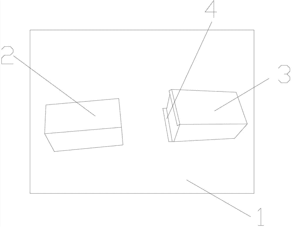
[0010] like figure 1 As shown, a clamping jig includes a square seat 1, a fixed claw 2 and a horizontally movable claw 3, the fixed claw 2 is arranged on the square seat 1, and a slideway 4 is arranged on the square seat 1, The bottom of the horizontally moving jaw 2 is inserted into the slideway 4, and can move horizontally along the slideway 4, the fixed jaw 2 and the horizontally moving jaw 3 are located on the same straight line, and the fixed jaw 2 and the horizontally moving jaw The bayonet openings of the jaws 3 are arranged oppositely, and the length of the horizontally movable jaw 3 is greater than that of the fixed jaw 2 .

[0011] In the present invention, the product is placed between the two jaws, the position of the fixed jaw 2 remains fixed, the horizontally movable jaw 3 can move forward along the slideway 4, and the bayonets of the fixed jaw 2 and the...


PUM


Abstract

The invention discloses a clamping fixture which comprises a square seat. The clamping fixture is characterized by further comprising a fixed clamping jaw and a horizontal movable clamping jaw, the fixed clamping jaw and a slide are arranged on the square seat, the bottom of the horizontal movable clamping jaw is inserted into the slide and can horizontally move along the slide, the fixed clamping jaw and the horizontal movable clamping jaw are positioned on the same straight line, and bayonets of the fixed clamping jaw and the horizontal movable clamping jaw are opposite. The clamping fixture solves the problems that a three-jaw chuck in the prior art only clamps circular products, materials in other shapes need to be machined by a CNC (computerized numerical control) milling machine, a machining process is complicated, working efficiency is low, and time and money are wasted. The clamping fixture is simple in structure, convenient to use and capable of clamping products in optional shapes.

Description

technical field [0001] The invention relates to a jig, in particular to a clamping jig. Background technique [0002] The use of fixtures is to ensure product quality, improve work efficiency, and expand the process range of machine tools. If you want to get high-quality parts, you need to perform high-precision positioning and clamping on the parts during processing, so turning is a very important and effective means. However, the traditional three-jaw chuck only clamps circular products, and other shapes need to be processed by a CNC milling machine. Using a CNC milling machine to process is complicated, low work efficiency, and time-consuming. Contents of the invention [0003] In order to solve the problem that the products clamped by the three-jaw chuck in the prior art are limited to circular products, and other shapes of materials need to be processed by a CNC milling machine, the processing technology is complicated, the work efficiency is low, and the problems of...

Claims


Application Information

Patent Timeline
IPC IPC(8): B23Q3/00
Inventor 蔡青春
Owner KUSN MAIZHI FIXTURE TECH
Learn More