Vibrating screen ore-feeding device

A vibrating screen and ore feeding technology, applied in the direction of screen, solid separation, grid, etc., can solve the problems of uneven load, large fluctuation of ore output, large machine vibration, etc., to improve efficiency and operation rate, and reduce machine failure. , Effective use of space

Active Publication Date: 2013-04-17
TAIYUAN IRON & STEEL GROUP
View PDF5 Cites 5 Cited by
  • Summary
  • Abstract
  • Description
  • Claims
  • Application Information

AI Technical Summary

Problems solved by technology

[0003] Defects of the original imported vibrating screen feeding device: (1) In the process of use, the original imported vibrating screen frequently has problems such as large fluctuations in ore feeding, uneven feeding, low classification efficiency, and large machine vibration; The ore feeding box only uses five holes on the side of the rectangular ore feeding box for simple ore feeding, without adjusting the screw rod, it can neither achieve uniform ore feeding, nor can it adjust the size of the ore feeding flow, causing the imported vibrating screen to receive ore in five channels. Different, low classification efficiency, uneven load, large machine vibration and other problems; (3) The fatal disadvantage of the original rectangular ore feeding box is that it cannot control the size of the ore feeding flow, and cannot realize central ore feeding and uniform ore output. During the process, there are often problems such as uneven feeding of ore pulp, large fluctuations in ore output, short service life, large space occupation, and ore leakage. Moreover, problems such as low classification efficiency of imported vibrating screens, uneven loads, and large machine vibrations are caused.

Method used


Image

  • Vibrating screen ore-feeding device
  • Vibrating screen ore-feeding device

Examples


Embodiment 1

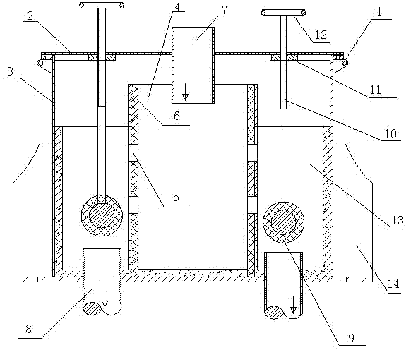
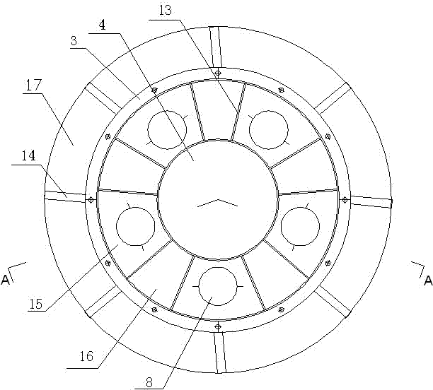
[0028] Such as figure 1 , 2 As shown, there are five vibrating screen feeding devices in the mining area, including a fully enclosed cylindrical box 3, a sealing cover 2 above the box 3, and a triangular lifting hole 1 on both sides of the sealing cover 2, and the sealing cover 2 The central part is provided with a splash-proof sealing door and an ore feeding pipe 7; a central cylinder 4 for buffering ore slurry is provided in the middle of the box body 3, and an ore outlet hole 5 is provided on the side wall of the central cylinder 4; ten blocks are arranged outside the central cylinder 4 The ore separation plate 13 divides the casing into five ore separation areas 16 and five ore output areas 15, each ore output area 15 below is provided with an ore output pipe 8, and the outer end outlet of the ore output pipe 8 is set to a fan shape; 8 is provided with a wear-resistant composite ore feeding ball valve 9, and the top of the ore ball valve 9 is connected with an adjusting s...

Embodiment 2

[0042] Vibrating screen feeding device with six mining areas:

[0043] Around the bottom of the cylinder body of the ore feeding device, a total of 12 ore separation plates are used to divide it into six ore discharge areas and six ore separation areas. The feature is that in order to ensure uniform ore discharge, the corresponding center angle of the ore discharge area is 40°, and the shape of the fan-shaped separation area Inner diameter / outer diameter × sector angle = (Φ450~Φ600) / (Φ800~Φ1500) mm×20°, the purpose is to ensure uniform ore discharge around the ore feeding device and strengthen the strength between the central cylinder and the ore feeding device cylinder ; The mine pipe is designed at the bottom of each mining area. All the other parts are the same as in Embodiment 1.

Embodiment 3

[0045] Vibrating screen feeding device with eight mining areas:

[0046] A total of 16 ore separation plates are used around the bottom of the cylinder of the ore feeding device to divide it into eight mining areas and eight separation areas. The feature is that in order to ensure uniform ore extraction, the corresponding center angle of the ore output area is 30°, and the shape of the fan-shaped separation area Inner diameter / outer diameter × sector angle = (Φ450~Φ600) / (Φ800~Φ1500) mm×15°, the purpose of which is to ensure uniform ore discharge around the ore feeding device and strengthen the strength between the central cylinder and the ore feeding device cylinder ; The mine pipe is designed at the bottom of each mining area. All the other parts are the same as in Embodiment 1.


PUM

PropertyMeasurementUnit
Volumeaaaaaaaaaa
Sizeaaaaaaaaaa
Dimensionsaaaaaaaaaa

Abstract

The invention relates to a vibrating screen ore-feeding device which is characterized in that the vibrating screen ore-feeding device comprises a totally enclosed cylindrical box; a sealing cover is arranged above a cylindrical box; triangle lifting holes are formed on bilateral sides of the sealing cover and a spray-proof sealing door and an ore-feeding pipe are arranged in the center of the sealing cover; the middle of the cylindrical box is provided with a buffering ore pulp feeding center cylinder and an ore discharging hole is formed on the lateral wall of a center cylinder; the inner wall of the cylindrical box, the bottom of the cylindrical box, the inner wall of a center cylinder and the outer wall of a center cylinder are respectively provided with a wear-resistant plate; the outer side of a center cylinder is provided with 2N ore separating plates which separate the cylindrical box into N ore separating areas and N ore discharging areas, the lower portion of every ore discharging area is provided with an ore discharging pipe, and an outlet of the external end of every ore discharging pipe is arranged into a fan shape; a wear-resistant composite ore-feeding ball valve is arranged above every ore discharging pipe and an adjusting screw rod, an adjusting nut and a hand wheel are connected above every ore-feeding ball valve; and eight trapezoidal reinforcing-rib plates are uniformly arranged outside the cylindrical box along a periphery. The vibrating screen ore-feeding device has the advantages of achieving the uniform ore-feeding operation, improving the screening efficiency, being capable of automatically adjusting the flow of ore pulp and good in wear resistance and extending the service life.

Description

technical field [0001] The invention relates to a vibrating screen ore feeding device, which belongs to the field of mine beneficiation machinery. Background technique [0002] Taigang Ekou Iron Mine uses 13 sets of Derrick 2SG48-60W-5STK five-way high-frequency vibrating screens imported from the United States (hereinafter referred to as imported vibrating screens, 2 means double vibrator, SG means super cracity strong vibration, exciting force 7.3g, W Indicates wet sieve, 5 indicates five-way, STK indicates stack overlap), classifies iron ore slurry with a particle size of 0-0.5 mm and a concentration of 35%-45%, with a processing capacity of 100-120t / h, using a stainless steel sieve Net, with a sieve size of 0.075×0.075mm, is the "throat" equipment for iron ore slurry classification. The qualified products under the screen enter the next process of magnetic separation, and the unqualified iron ore powder on the screen enters the ball mill for regrinding, so automatically ...

Claims


Application Information

Patent Timeline
IPC IPC(8): B07B1/46B07B1/28
Inventor 何铁牛胡丽丽张天翔
Owner TAIYUAN IRON & STEEL GROUP
Why Eureka
Try Eureka