Comb bar for a suction nozzle for a workstation of a textile machine for creating cross-wound spools

A cross-winding bobbin and needle row technology, which is applied in the direction of thin material handling, conveying filamentous materials, transportation and packaging, etc., can solve the problems of the device not being implemented, and achieve the effect of improving looseness

Inactive Publication Date: 2013-04-10
SAURER GERMANY GMBH & CO KG
View PDF9 Cites 2 Cited by
  • Summary
  • Abstract
  • Description
  • Claims
  • Application Information

AI Technical Summary

Problems solved by technology

In practice, however, the relatively complex and sensitive device disclosed by AT-PS 368 106 has not been implemented

Method used


Image

  • Comb bar for a suction nozzle for a workstation of a textile machine for creating cross-wound spools
  • Comb bar for a suction nozzle for a workstation of a textile machine for creating cross-wound spools
  • Comb bar for a suction nozzle for a workstation of a textile machine for creating cross-wound spools

Examples


Embodiment Construction

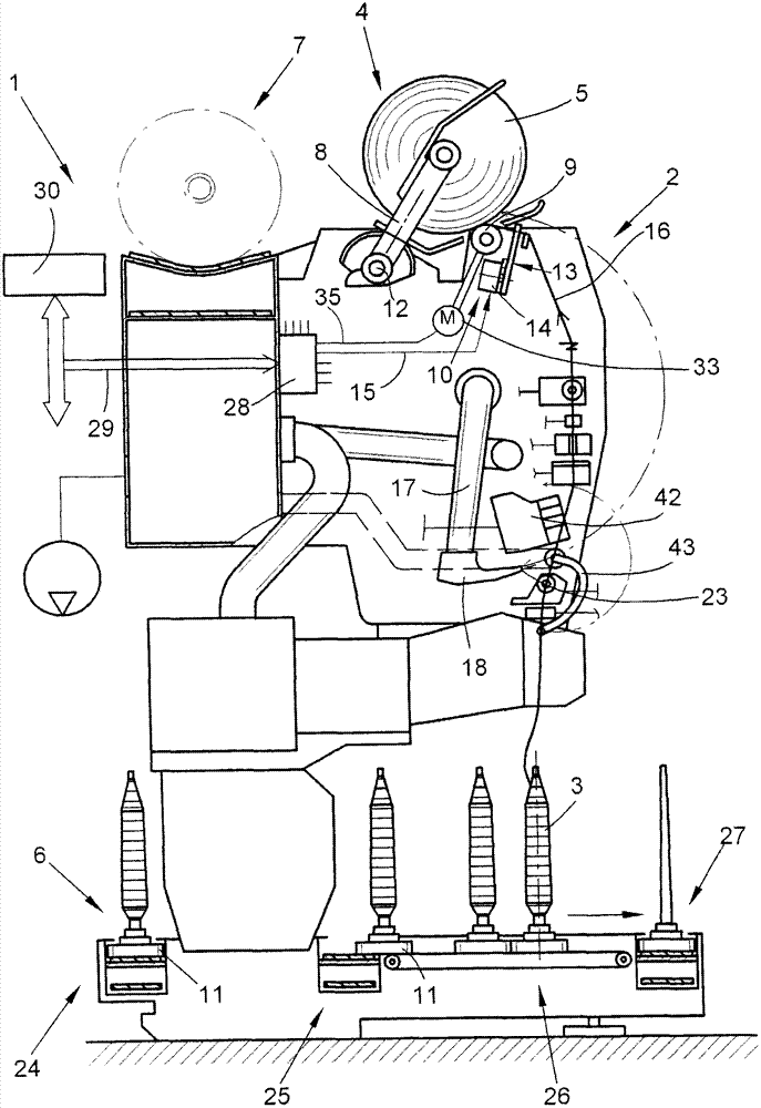
[0026] figure 1 A station 2 of a textile machine for producing cross-winding bobbins, which in this exemplary embodiment is a so-called automatic cross-winding device 1 , is shown schematically in side view. Such an automatic crosswinding device 1 usually has a large number of such stations 2 of the same type arranged side by side. As known without further explanation, at these stations 2 the spinning packages 3 produced on the ring spinning machine are rewound into cross-wound packages 5 of large packages. After the cross-wound bobbin 5 has been produced, it is transferred to the cross-wound bobbin transfer device 7 arranged in the longitudinal direction of the machine by means of a (not shown) automatically working service unit (preferably a cross-wound bobbin changer) and conveyed To the bobbin loading station set on the end side of the machine, etc.

[0027] As shown in the exemplary embodiment, such an automatic crosswinder 1 usually also has a supply device in the form...


PUM


Abstract

The invention relates to a comb bar for a suction nozzle for a workstation of a textile machine for creating cross-wound spools. The suction nozzle has a suction port for the pneumatic picking of a yarn breakage or a controlled thread cut accumulated on the surface of a cross-wound bobbin end. The comb bar disposed in the suction port area is provided with a chamfer and a comb strip. The comb strip is used for fixing the thrum. The comb bar (19) has a structured surface (32) formed at a region of a chamfer (31) of the bar during photochemical etching process. Contour edges are formed at a region of the structured surface and comprise undercuts. The structured surface is produced by means of photochemical etching.

Description

technical field [0001] The invention relates to a needle row of suction nozzles for a station of a textile machine for producing cross-wound bobbins according to the preamble of claim 1 . Background technique [0002] In connection with the operation of textile machines for the manufacture of cross-wound bobbins, in particular automatic cross-winders, it has always been common that when the winding is interrupted, e.g. In the case of bobbin feeding, the automatic installation of the yarn connection of the station itself is activated by the station computer. [0003] That is to say, as described in DE 40 05 752 A1, the workstation computer is responsible for firstly placing the so-called suction nozzle with its suction opening on the surface of the winding bobbin slowly rotating counter to the winding direction and applying a negative pressure. Here, the suction nozzle attempts to pick up, with its suction opening, the yarn end of the upper yarn pneumatically from the surfac...

Claims


Application Information

Patent Timeline
Patent Type & Authority Applications(China)
IPC IPC(8): B65H67/08
CPCB65H2701/31B65H67/085
Inventor U·霍尔特F·科林根
Owner SAURER GERMANY GMBH & CO KG
Why Eureka
Try Eureka