
Spiral conveyer

A screw conveyor and screw blade technology, which is applied in the field of conveyors and screw conveyors, can solve problems such as limited conveying capacity, and achieve the effects of strong conveying capacity, convenient processing and maintenance, and high conveying efficiency

Inactive Publication Date: 2013-04-10
溧阳市保珠建材厂
View PDF2 Cites 1 Cited by
  • Summary
  • Abstract
  • Description
  • Claims
  • Application Information

AI Technical Summary

Problems solved by technology

Its main disadvantage: there is only one blade shaft, and the conveying capacity is limited

Method used


Image

  • Spiral conveyer
  • Spiral conveyer
  • Spiral conveyer

Examples


Embodiment 1

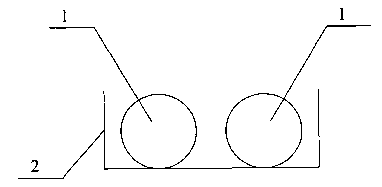
[0019] Such as figure 1 As shown, a screw conveyor includes a trough 2 and two helical blades 1 , and the two helical blades 1 are located in the chute 2 .

[0020] When running, the two helical blades 1 can be opened separately or simultaneously according to needs, so as to effectively improve the conveying capacity.

Embodiment 2

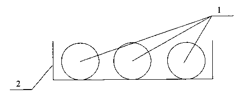
[0022] Such as figure 2 As shown, a screw conveyor includes a trough 2 and three helical blades 1 , and the three helical blades 1 are all located in the chute 2 .

[0023] When running, the three helical blades 1 can be opened separately or simultaneously according to needs, so as to effectively improve the conveying capacity.

Embodiment 3

[0025] Such as image 3 As shown, a screw conveyor includes a trough 2 and four helical blades 1 , and the four helical blades 1 are all located in the chute 2 .

[0026] When running, the four helical blades 1 can be opened separately or simultaneously according to needs, so as to effectively improve the conveying capacity.

[0027] In fact, the number of helical blades 1 can be matched and determined according to the width of the trough 2, and the number of helical blades 1 is ≥ 2. Further, the number of spiral blades 1 is preferably 3 to 6, which is convenient for processing and maintenance.


PUM


Abstract

The invention relates to a conveyer, in particular to a spiral conveyer. The spiral conveyer provided by the invention comprises spiral blades (1) and a material groove (2); and the spiral blades (1) are located inside the material groove (2). The quantity of the spiral blades (1) is more than or equal to two. Furthermore, the quantity of the spiral blades (1) is three to six. With the adoption of the technical scheme, the spiral conveyer provided by the invention has the following beneficial effects that (1) a plurality of the spiral blades are used, and are located in the material groove, the delivery capacity of the spiral conveyer can be effectively improved, the delivery capacity is strong, the delivery quantity is large, and the delivery efficiency is high; and (2) the quantity of the spiral blades is three to six, the quantity is suitable, and the spiral conveyer is convenient to machine and maintain.

Description

technical field [0001] The invention relates to a conveyor, in particular to a screw conveyor. The invention belongs to the technical field of mechanical equipment manufacturing and processing. Background technique [0002] The screw conveyor is a kind of conveying equipment that uses the rotation of the helical blade to push the material to move along the trough to complete the horizontal, inclined or vertical conveying task. Its working principle: the blade rotates in the trough to push the material to move forward along the trough by overcoming gravity, friction on the trough and other resistances. [0003] Existing screw conveyors such as Figure 4 As shown: it is mainly composed of a helical blade 1 and a matching trough 2. [0004] Chinese Patent Publication No. CN2663361Y discloses a screw conveyor, which is mainly used for mixing and conveying asphalt and other materials. Wheel, discharge port, feed port, the conveying blade on the main shaft is left-handed, a ci...

Claims


Application Information

Patent Timeline
Patent Type & Authority Applications(China)
IPC IPC(8): B65G33/10
Inventor 葛保珠
Owner 溧阳市保珠建材厂
Learn More