
Drive motor control system and control method of laser-boring optical element

A technology for driving motor control and optical components, which is used in laser welding equipment, manufacturing tools, welding equipment, etc., and can solve problems such as the error between the motor speed ratio and the preset value, and the inability to guarantee the accuracy of graphics.

Active Publication Date: 2013-04-10
CHINA KEHAN LASER FUJIAN
View PDF7 Cites 10 Cited by
  • Summary
  • Abstract
  • Description
  • Claims
  • Application Information

AI Technical Summary

Problems solved by technology

However, due to problems such as the control cycle of the host computer and the response of the motors, certain following errors will inevitably occur when the host controller is used to control each motor separately. If there is an error between the ratio and the preset value, the accuracy of the scanned graphics cannot be guaranteed

Method used


Image

  • Drive motor control system and control method of laser-boring optical element
  • Drive motor control system and control method of laser-boring optical element
  • Drive motor control system and control method of laser-boring optical element

Examples


Embodiment Construction

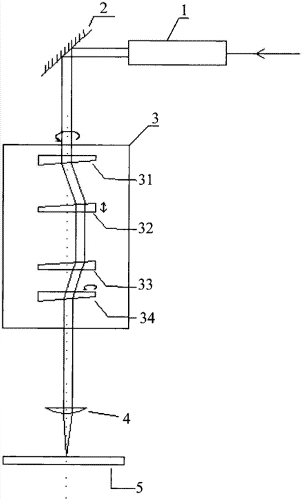
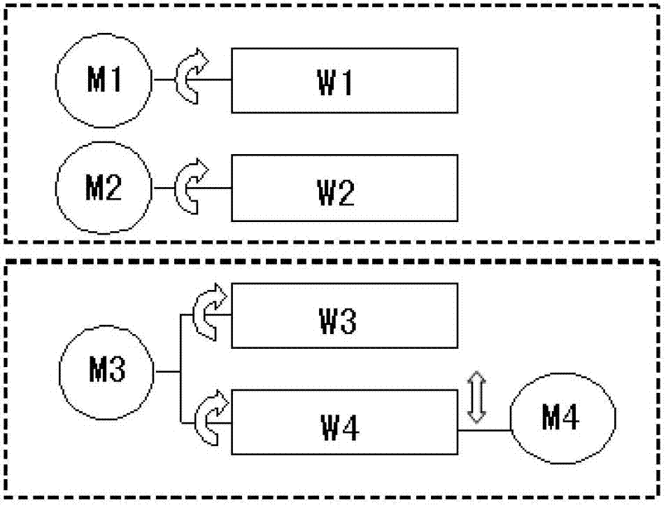
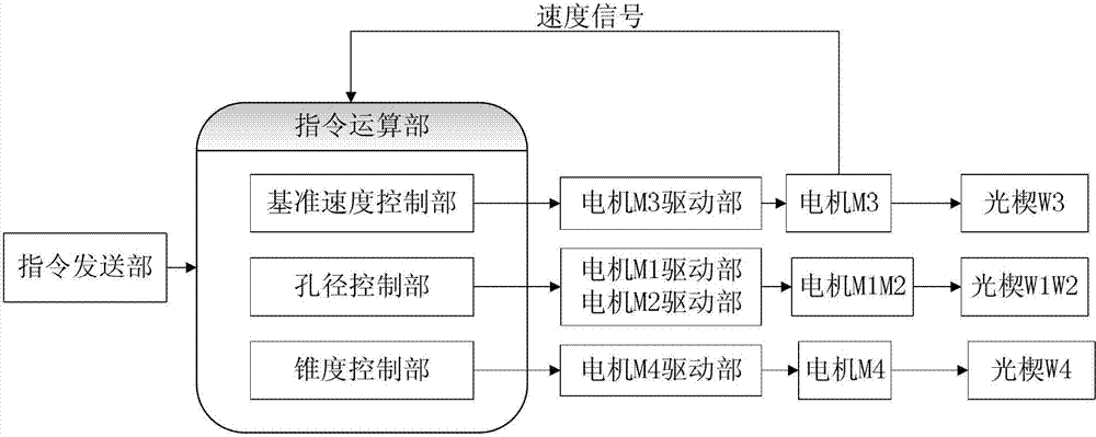
[0035] Such as figure 2 As shown, the controlled object of the present invention is as figure 2 Shown is: four motors M1-M4 that drive the four optical wedges 1-4 to move. Among them: the optical wedges W1 and W2 are driven by the motors M1 and M2 respectively, and the optical wedges W3 and W4 are both driven by the motor M3 to rotate. At the same time, the optical wedge W4 can also move up and down through the drive of the motor M4 to pull apart the optical wedge. The distance between W3. It can be seen from the optical principle that when rotating, if the deviation angle is formed between the optical wedges W1 and W2, the rotating beam will produce a radius of rotation; if the distance between the optical wedges W3 and W4 along the optical axis makes the rotating light speed A lateral displacement is generated, and after passing through the focusing mirror, a beam of rotating light with a taper will be formed.

[0036] Such as image 3 Shown: the control system of the ...


PUM


Abstract

The invention discloses a drive motor control system with a plurality of optical wedges. The drive motor control system comprises an instruction sending part, an instruction operating part, a motor drive part, a plurality of motors and the plurality of optical wedges, wherein the instruction sending part is used for sending an initial instruction value to the instruction operating part; the instruction operating part is used for receiving an instruction signal sent by the instruction sending part, and generating an operation speed signal of the motors according to a fed-back real-time speed signal of the motors; and the motor drive part drives the motors to operate according to the operation speed signal sent by the instruction operating part, so that the motors drive the optical wedges to rotate. The instruction operating part comprises a reference speed control part, a bore diameter control part and a conical degree control part. The reference speed of the rotation of the whole optical wedge system is controlled by the speed control part; the turning radius of a light beam is changed by the bore diameter control part during a rotating process of the optical wedges; and the conical degree formed by rotating the light beam is changed by the conical degree control part.

Description

technical field [0001] The invention belongs to the field of laser processing, and in particular relates to a motor control system and a control method of an optical element for laser drilling. Background technique [0002] A prism with a small refraction angle is called an optical wedge, and a double optical wedge is composed of two adjacent optical wedges with the same refractive index and equal refraction angle. When the laser is drilling, the motor drives the two optical wedges to rotate synchronously, so that the laser scans under the action of the double optical wedges. According to the existing theory, if the refraction angle α of the optical wedge and the incident angle of the light are small, the deflection angle is δ=(n-1)α, so the relative movement of the two optical wedges can produce different scanning patterns, these Features have been used increasingly widely. In the traditional dual optical wedge control, the upper controller and its software are usually us...

Claims


Application Information

Patent Timeline
IPC IPC(8): B23K26/08B23K26/38B23K26/082B23K26/382
Inventor 江浩杨小君赵卫
Owner CHINA KEHAN LASER FUJIAN
Learn More