
Device and method for monitoring a photovoltaic system

A technology of photovoltaic equipment and photovoltaic modules, which is applied in the direction of measuring devices, photovoltaic modules, photovoltaic power generation, etc., can solve the problems of photovoltaic module efficiency decline and other problems, and achieve good scalability, precise positioning, and reliable detection of events.

Active Publication Date: 2013-04-03
SMA SOLAR TECH AG
View PDF8 Cites 4 Cited by
  • Summary
  • Abstract
  • Description
  • Claims
  • Application Information

AI Technical Summary

Problems solved by technology

[0009] - a drop in efficiency (degradation) of one or more photovoltaic modules;

Method used


Image

  • Device and method for monitoring a photovoltaic system
  • Device and method for monitoring a photovoltaic system
  • Device and method for monitoring a photovoltaic system

Examples


Embodiment Construction

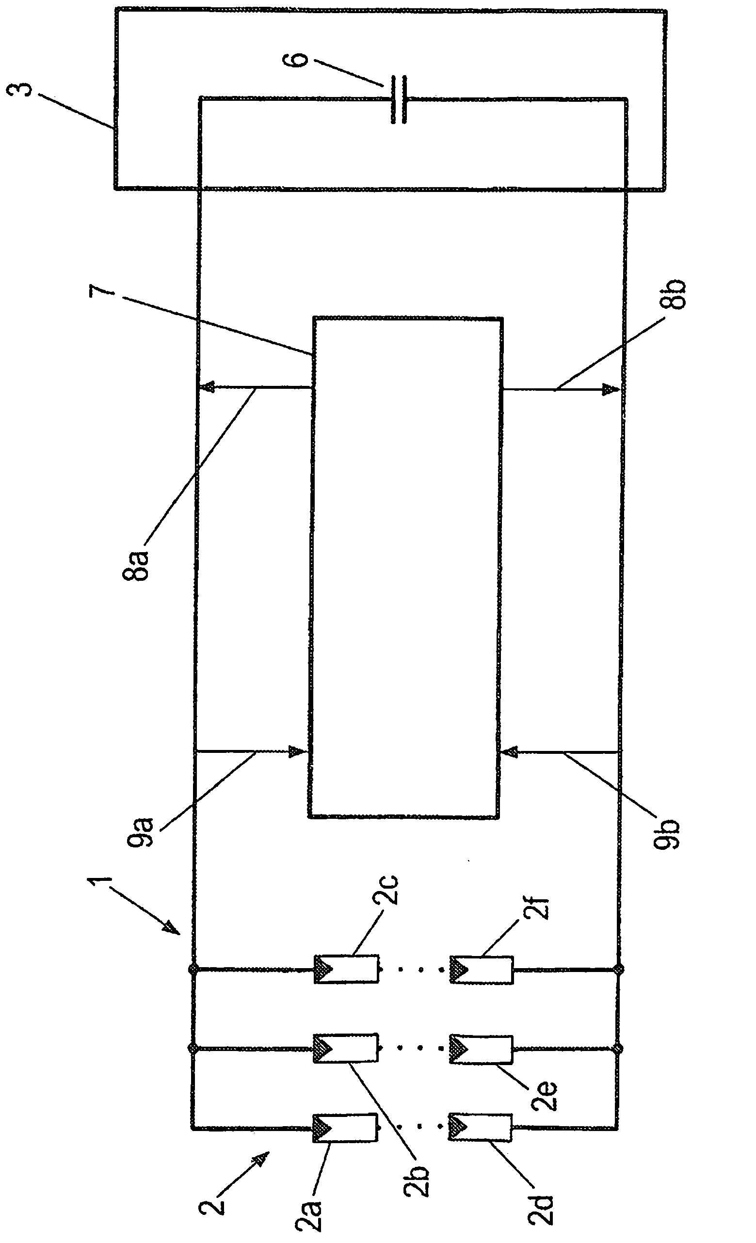
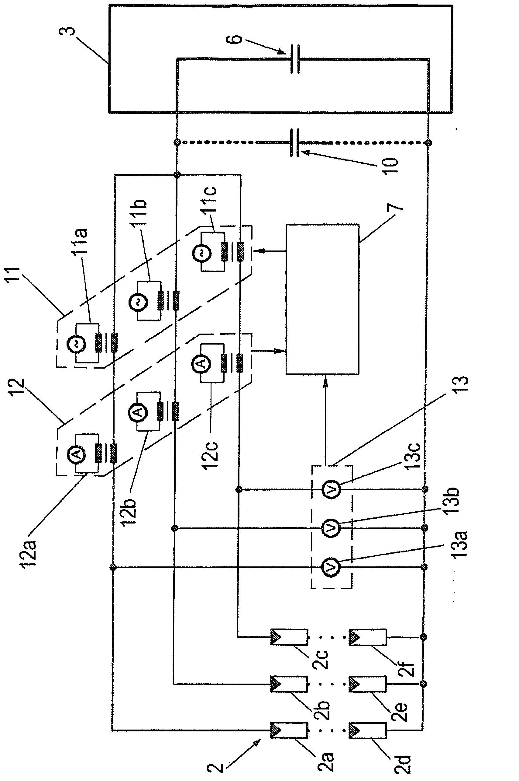
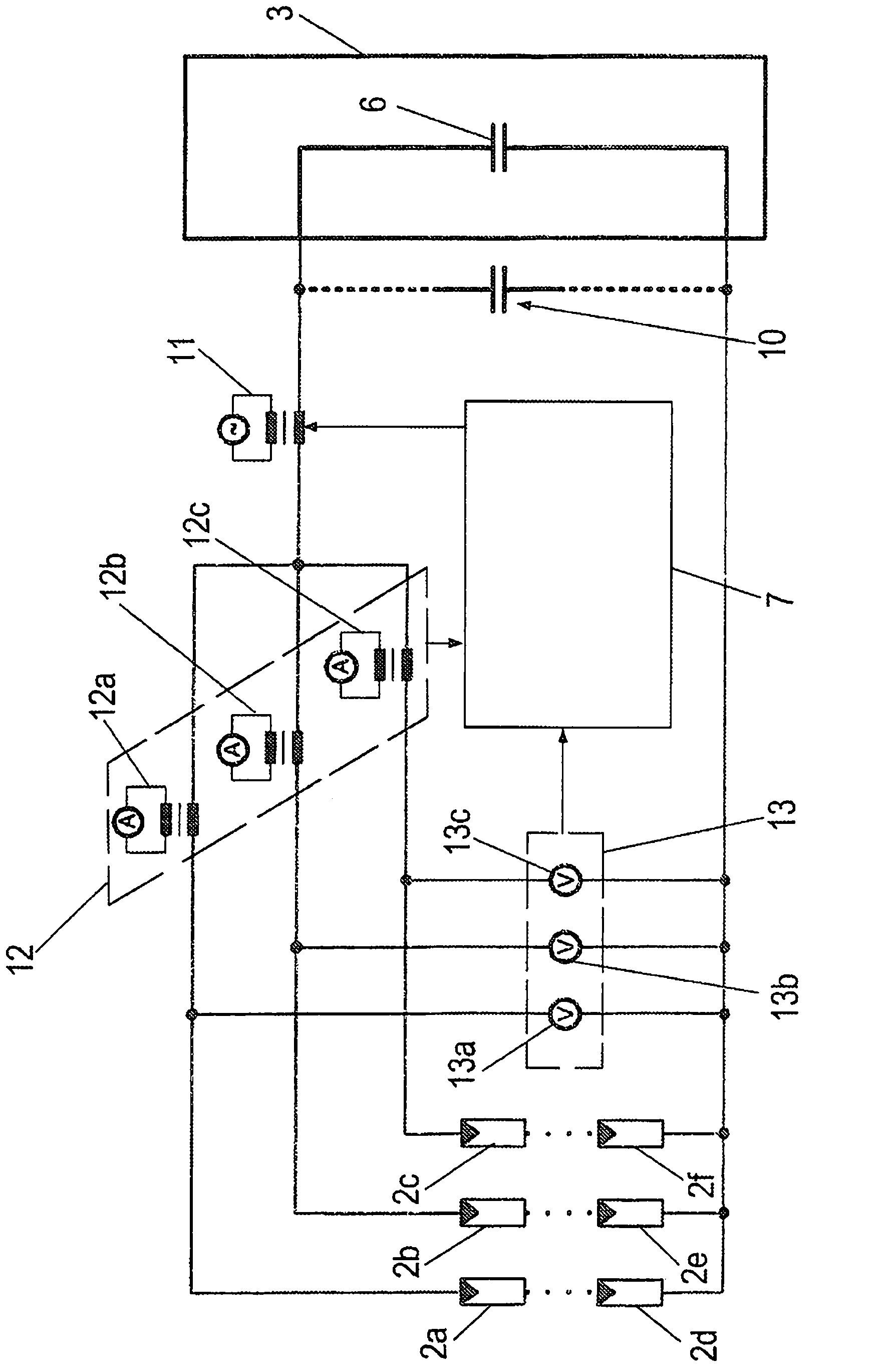
[0037] figure 1 The photovoltaic system 1 is shown as an example in the form of a circuit diagram. The photovoltaic system 1 comprises a photovoltaic generator 2 which has a plurality of photovoltaic modules 2 a to 2 f on its side.

[0038] In the context of the present application, a photovoltaic generator 2 is referred to as the part of the photovoltaic system 1 that converts radiation energy into electrical energy. The photovoltaic generator 2 can have only one single photovoltaic module up to a large number of photovoltaic modules 2a to 2f. The photovoltaic modules 2 a - 2 f may be wired and / or arranged in different ways within the photovoltaic generator 2 . For example in figure 1 In the embodiment of FIG. 2 , each plurality of photovoltaic modules are connected in series to form a so-called string (String), for the sake of clarity, only two photovoltaic modules 2a and 2d, 2b and 2e or 2c and 2f are shown for each string. A total of three strings are formed here, whic...


PUM


Abstract

The invention relates to a device for monitoring a photovoltaic system (1) in order to detect the occurrence of events that impair the intended operation of the photovoltaic system (1), comprising a photovoltaic generator (2) having a first group of photovoltaic modules (2a) and a second group of photovoltaic modules (2b-f), which is different from the first group. The device also comprises a first and a second coupling agent pair, both pairs comprising signal input elements (11a-c, 17) for inputting a test signal into the photovoltaic generator and a signal output element (12a-c, 13a-c) for outputting a response signal, wherein the first coupling element pair is arranged in such a way that the first coupling element pair can detect the occurrence of events selectively in the first group of photovoltaic modules (2a), and the second coupling element pair is arranged in such a way that the second coupling element pair can detect the occurrence of events selectively in the second group of photovoltaic modules (2b-f). The invention further relates to a method for monitoring a photovoltaic system (1) having two or more photovoltaic modules (2a-f).

Description

technical field [0001] The invention relates to a device and a method for monitoring a photovoltaic installation. Background technique [0002] Photovoltaic devices provide electrical energy by means of photovoltaics. [0003] During operation of the photovoltaic system, high currents can occur which, in conjunction with faulty and / or damaged photovoltaic system components, can lead to enormous power losses. This relates in particular to the mutual contact resistance of the contacts at the connection points of the modules as well as the electrical line terminations. [0004] To ensure regular operation, photovoltaic installations need to be monitored to identify the occurrence of events that prevent the regular operation of the equipment. [0005] Such events could be, for example: [0006] - One or more components of photovoltaic equipment are stolen; [0007] - damage to one or more components of the photovoltaic device; [0008] - changes in conductivity of one or mo...

Claims


Application Information

Patent Timeline
Patent Type & Authority Applications(China)
IPC IPC(8): G01R31/26G08B13/14H01L31/02
CPCG01R31/2605G01R31/405G08B13/1409H02S50/10Y02E10/50G01R31/2642
Inventor M·霍普夫H·贝伦茨G·贝藤沃特S·比尼克M·卡拉图彻维利
Owner SMA SOLAR TECH AG
Learn More