
Light emitting diode (LED) pulse drive circuit and drive method thereof

A technology of pulse drive and drive circuit, which is applied in the direction of electric lamp circuit layout, electric light source, lighting device, etc., can solve the problems of low life expectancy of LED, mismatch of service life and long service life, etc., to achieve The effect of long service life, extended service life and low cost

Inactive Publication Date: 2013-04-03
SOUTH CHINA UNIV OF TECH
View PDF4 Cites 6 Cited by
  • Summary
  • Abstract
  • Description
  • Claims
  • Application Information

AI Technical Summary

Problems solved by technology

[0002] LED (Light Emitting Diode, Light Emitting Diode) is a solid-state semiconductor device that can convert electrical energy into visible light. It can directly convert electricity into light. LED has the advantages of energy saving, environmental protection, small size and long service life. It is currently the most The ideal light source to replace the traditional lighting source has a wide range of uses; and the driving circuit is a key factor to ensure the long life of the LED and other performances. At present, although the life of the LED reaches 50,000 hours or longer, the existing The service life of the constant current LED drive circuit is very short, and it is difficult to exceed 10,000 hours, which is far from the service life of the LED. The main reason why the service life of the LED drive circuit does not match the service life of the LED is: The life of the electrolytic capacitor of energy and voltage stabilizing components is generally only 5,000 to 10,000 hours under rated working conditions, which directly leads to the fact that the actual service life of the LED is much lower than the expected life, and due to cost factors, other capacitors cannot replace electrolytic capacitors. In addition, The greater the output power of the constant current drive circuit, the greater the capacity of the required electrolytic capacitor, resulting in a large drive circuit and high cost; in order to improve the service life of the LED, reduce the drive circuit volume and reduce costs, it is necessary to break through the existing technology. Developed and manufactured an LED drive circuit without electrolytic capacitors

Method used


Image

  • Light emitting diode (LED) pulse drive circuit and drive method thereof
  • Light emitting diode (LED) pulse drive circuit and drive method thereof

Examples


Embodiment

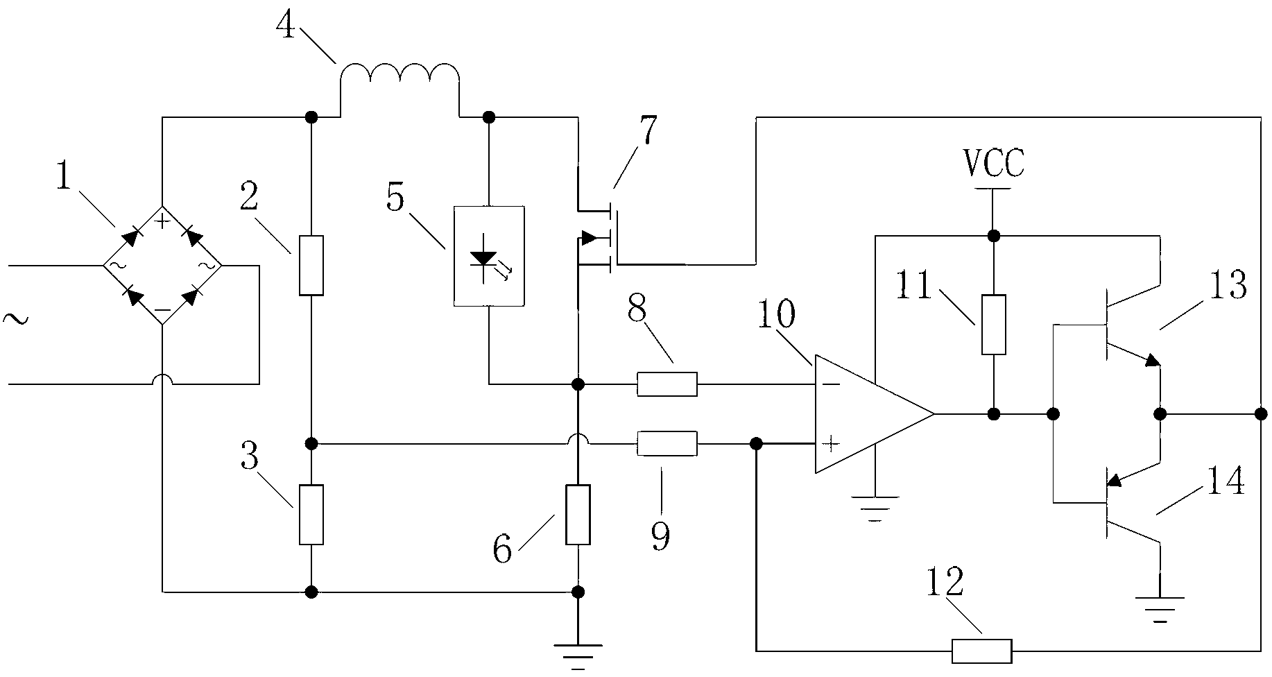
[0023] Such as figure 1 As shown, a LED pulse drive circuit includes a rectifier bridge 1, the rectifier bridge 1 has an input end and an output end, and the output end has a positive pole and a negative pole, and the LED pulse drive circuit also includes a control circuit, a switch tube drive Circuit, inductance 4, switch tube 7, LED module 5, first resistor 2, second resistor 3 and third resistor 6; one end of inductance 4 and one end of first resistor 2 are connected to the positive pole of the output end of rectifier bridge 1, The negative pole of the output terminal of the rectifier bridge 1 is connected to the reference ground, the input terminal of the rectifier bridge 1 is connected to the 220-volt single-phase AC mains, the drain of the switch tube 7 and the anode of the LED module 5 are connected to the other end of the inductor 4, and the LED module 5 The cathode of the switch tube 7 and the source of the switch tube 7 are all connected to one end of the third resis...


PUM


Abstract

A light emitting diode (LED) pulse drive circuit comprises a rectifier bridge, a control circuit, a switching tube drive circuit, an inductor, a switching tube, an LED module and a plurality of resistors. A drive method of the LED pulse drive circuit comprises that step 1, the switching tube is conducted and the current in a loop rises; steps 2, the resistors are used for conducting partial pressure for the output voltage of the rectifier bridge, the reference voltage is obtained, the resistors are used for sampling the current, the sampling voltage is obtained, the sampling voltage is compared with the reference voltage through a voltage comparer, when the sampling voltage is higher than the reference voltage, the voltage comparer outputs the low level, the switching tube is disconnected and the current in the loop falls; step 3, when the sampling voltage is lower than the reference voltage, the voltage comparer outputs the high level and the switching tube is conducted; and step 4, the step 1, the step 2 and the step 3 are conducted repeatedly, the current passing the LED is pulse current and the envelope of the pulse current is the waveform which is formed by the sine wave subjected to the full-wave rectification.

Description

technical field [0001] The invention relates to a pulse driving circuit technology, in particular to an LED pulse driving circuit and a driving method thereof. Background technique [0002] LED (Light Emitting Diode, Light Emitting Diode) is a solid-state semiconductor device that can convert electrical energy into visible light. It can directly convert electricity into light. LED has the advantages of energy saving, environmental protection, small size and long service life. It is currently the most The ideal light source to replace the traditional lighting source has a wide range of uses; and the driving circuit is a key factor to ensure the long life of the LED and other performances. At present, although the life of the LED reaches 50,000 hours or longer, the existing The service life of the constant current LED drive circuit is very short, and it is difficult to exceed 10,000 hours, which is far from the service life of the LED. The main reason why the service life of t...

Claims


Application Information

Patent Timeline
Patent Type & Authority Applications(China)
IPC IPC(8): H05B37/02
Inventor 王剑周平田联房
Owner SOUTH CHINA UNIV OF TECH
Learn More