
Device for measuring wind speed and direction

A technology of wind speed, wind direction and mounting seat, which is applied in the direction of measuring device, fluid speed measurement, speed/acceleration/impact measurement, etc. It can solve the problems of regular maintenance and calibration, limited application, high price, etc., and achieve accurate and reliable measurement accuracy. The effect of overcoming technical difficulties and simple and reasonable structure

Inactive Publication Date: 2013-04-03
CENT SOUTH UNIV
View PDF6 Cites 24 Cited by
  • Summary
  • Abstract
  • Description
  • Claims
  • Application Information

AI Technical Summary

Problems solved by technology

The probe of the thermal anemometer has certain disturbances to the flow field, and it also has the disadvantages of easy breakage of the hot wire and the need for regular maintenance and calibration, so its application is relatively limited
Although ultrasonic wind measurement has high measurement accuracy, it is more expensive and requires a higher installation location
However, the wind measuring instrument based on the force measurement method has not been seen in the market.
[0003] Some people are conducting research on cylinders and spheres to measure wind speed and direction, but cylinders and spheres will encounter aerodynamic problems when measuring wind speed and direction

Method used


Image

  • Device for measuring wind speed and direction
  • Device for measuring wind speed and direction
  • Device for measuring wind speed and direction

Examples


Embodiment 1

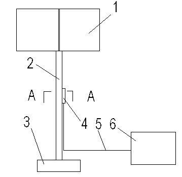
[0027] The windward force receiving body, the deformation rod 2 and the mounting seat 3 are assembled together sequentially from top to bottom; the sensor 4 is installed on the deformation rod 2, and the output end of the sensor 4 is electrically connected to the host computer 6 through a data line 5; the windward The force-receiving body is composed of two mutually perpendicular vertical plates 1 to form a rigid structure, and the two vertical plates 1 are three-dimensionally vertical and / or vertical to each other. The cross-section of the position where the sensor 4 is installed on the deformation rod 2 is rectangular. The sensors 4 installed on the four surfaces of the deformation rod 2 are tensile strain gauges 7, and the tensile strain gauges 7 are arranged on the same cross section.

Embodiment 2

[0029] On the basis of Embodiment 1, the sensor 4 installed on the deformation rod 2 is a pressure strain gauge 8 . Tensile strain gauges 7 and compressive strain gauges 8 on each face are arranged on the same cross section.

Embodiment 3-4

[0031] It is basically the same as the corresponding embodiment 1-2, except that the outer contour of the riser 1 is a rectangle.


PUM


Abstract

The invention discloses a device for measuring the wind speed and direction. The device comprises a windward force body, a transformation rod (2), a mount (3), a sensor (4), a data line (5) and a host computer (6) with special software, wherein the windward body force, the transformation rod (2) and the mount (3) are sequentially assembled from top to bottom, the sensor (4) is arranged on the transformation rod (2) and the output terminal of the sensor is electrically connected with the host computer (6) through the data line (5), and the windward force body is composed of two perpendicular vertical plates (1) which are mutually perpendicular in a three-dimensional interphase perpendicular and / or mutual penetration perpendicular mode. The cross-section of the portion of the transformation rod (2) where the sensor (4) is arranged is in rectangular structure. The sensor (4) is a tensile strain gage (7) or a tensile strain gage (7) and a pressure strain gage (8). The device for measuring the wind speed and direction has the advantages of simple and reasonable structure, solves the technical problems in relative technical field, and overcomes the technical problem of critical reynolds number, thereby obtaining more accurate and reliable measurement accuracy.

Description

technical field [0001] The invention relates to a device for measuring wind speed and direction. Background technique [0002] At present, wind measuring instruments on the market are mainly divided into two types: mechanical and non-mechanical. The mechanical type mainly includes the wind cup type and the propeller type, but due to the mechanical friction and the impact of sand and stone on the rotating parts in daily use, its service life is not high. Especially in the case of low-temperature icing, in the rare snowy and freezing weather in the history of 2008, a large number of mechanical anemometer wind vanes and wind cups in the affected provinces were frozen and could not rotate, resulting in the failure of the anemometer. Non-mechanical types mainly include thermal (hot wire, hot ball) and ultrasonic. The probe of thermal anemometer has certain disturbances to the flow field, and also has the disadvantages of easy breakage of the hot wire, and the need for reg...

Claims


Application Information

Patent Timeline
Patent Type & Authority Applications(China)
IPC IPC(8): G01P5/02G01P13/00
Inventor 田红旗梁习锋鲁寨军杨明智许平高广军姚松刘堂红杨志刚任鑫
Owner CENT SOUTH UNIV
Learn More