Head baffle of plate-fin heat exchanger

A technology of plate-fin heat exchanger and head, which is applied in the direction of heat exchanger shell, heat exchange equipment, lighting and heating equipment, etc., which can solve the problem of less application, complicated and over-dense arrangement of openings, and reduced baffle strength and other issues, to achieve the effect of expanding the scope of application, improving logistics distribution, and improving operational reliability

Inactive Publication Date: 2013-04-03
CHINA UNIV OF PETROLEUM (EAST CHINA)
View PDF4 Cites 5 Cited by
  • Summary
  • Abstract
  • Description
  • Claims
  • Application Information

AI Technical Summary

Problems solved by technology

For the improvement of the head structure, there are two ideas: the secondary head and the installation of perforated baffles. The secondary head structure can improve the uniformity of material distribution and heat exchange efficiency, but due to the limited performance improvement, and the head The increase of the overall shape of the structure is less used in engineering
The key to improving the logistics distribution characteristics of the head by adding perforated baffles is the arrangement of the baffle openings. The structure of the baffles with staggered holes has received great attention and research. This structure can significantly improve the distribution characteristics of the head. Improve the heat exchange efficiency, but the arrangement of openings in this structure is complicated and dense, which reduces the strength of the baffle, increases the difficulty of design and processing, and the current status of engineering application is not good; processing the perforated baffle into a curved surface can to a certain extent Improve the uniformity of logistics distribution, but the curved surface causes the deformation of the through hole, which reduces the strength of the baffle, and the difficulties in processing and installation make it difficult to popularize

Method used


Image

  • Head baffle of plate-fin heat exchanger
  • Head baffle of plate-fin heat exchanger
  • Head baffle of plate-fin heat exchanger

Examples


Embodiment Construction

[0017] In order to make the structure and working principle of the present invention clearer, the present invention will be further described below in conjunction with the accompanying drawings and embodiments.

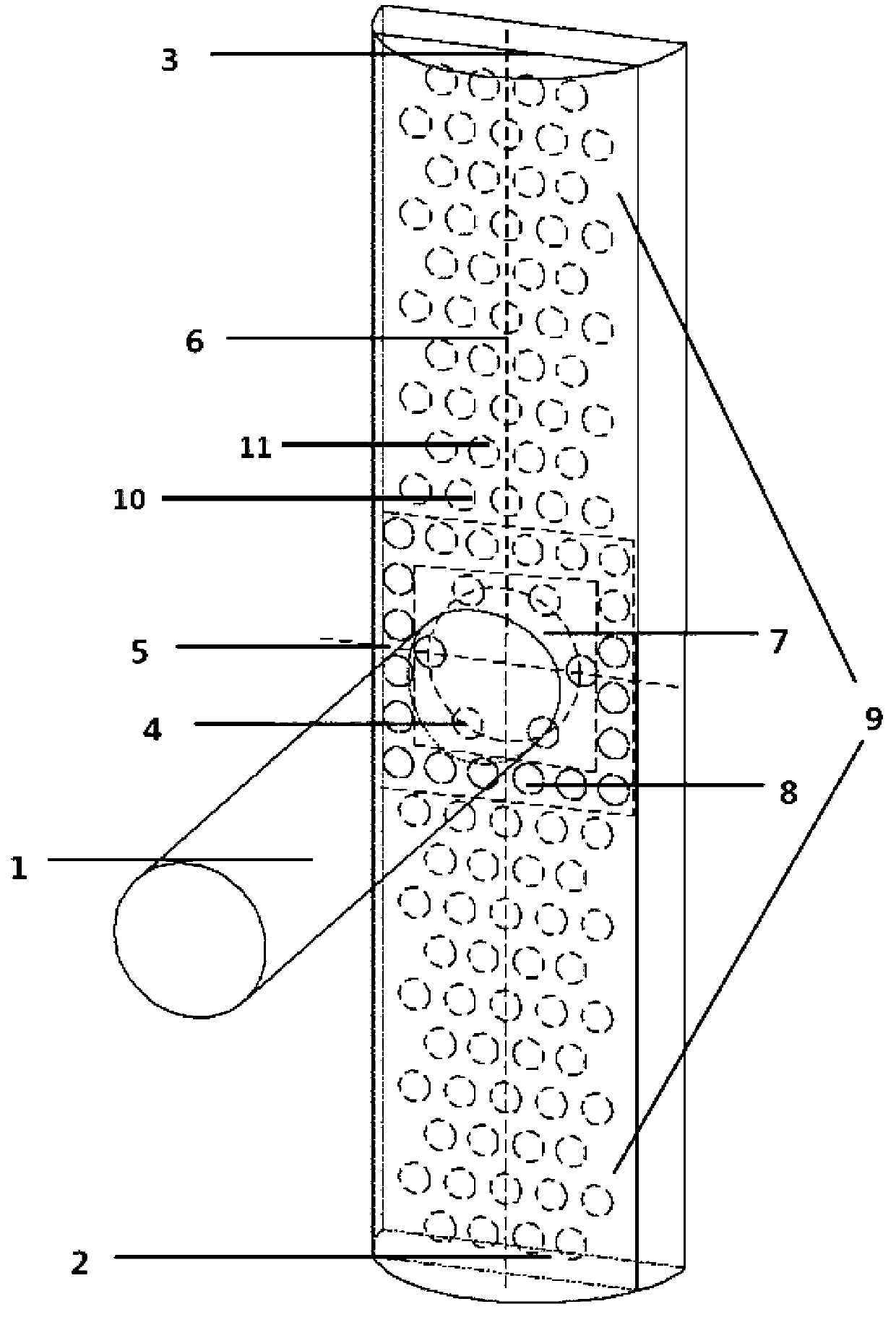
[0018] see figure 1 , according to the technical solution of the present invention, a baffle structure suitable for the head of a plate-fin heat exchanger, the rectangular baffle 3 is installed at 1 / 2 of the arc-shaped structure 2 of the head, and the recommended thickness of the baffle is 1 ~3mm, in actual application, it can be appropriately increased or decreased according to the fluid properties, Reynolds number and gas-liquid ratio and other parameters.

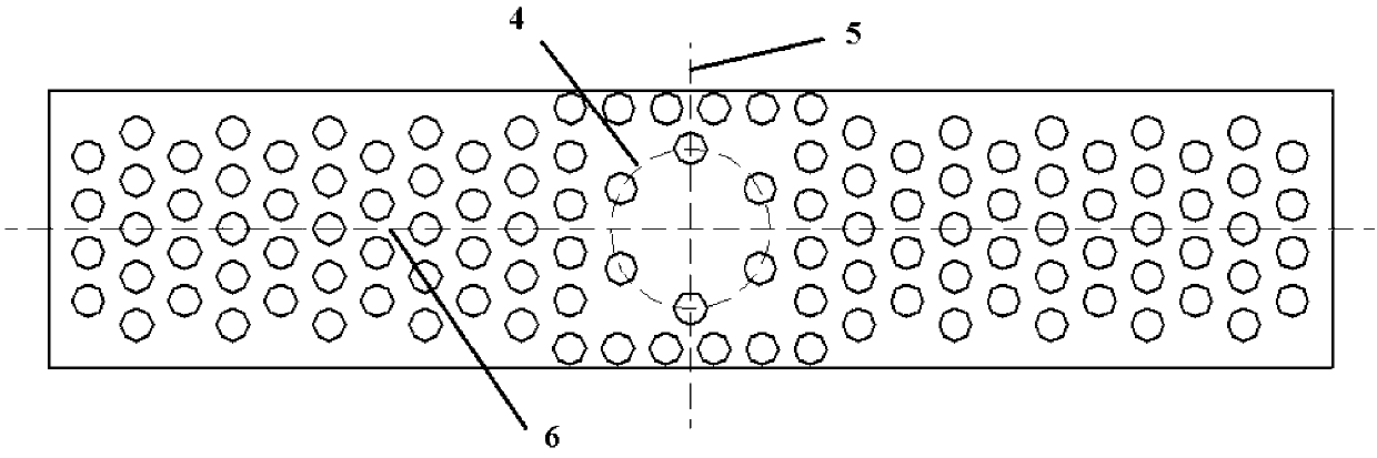
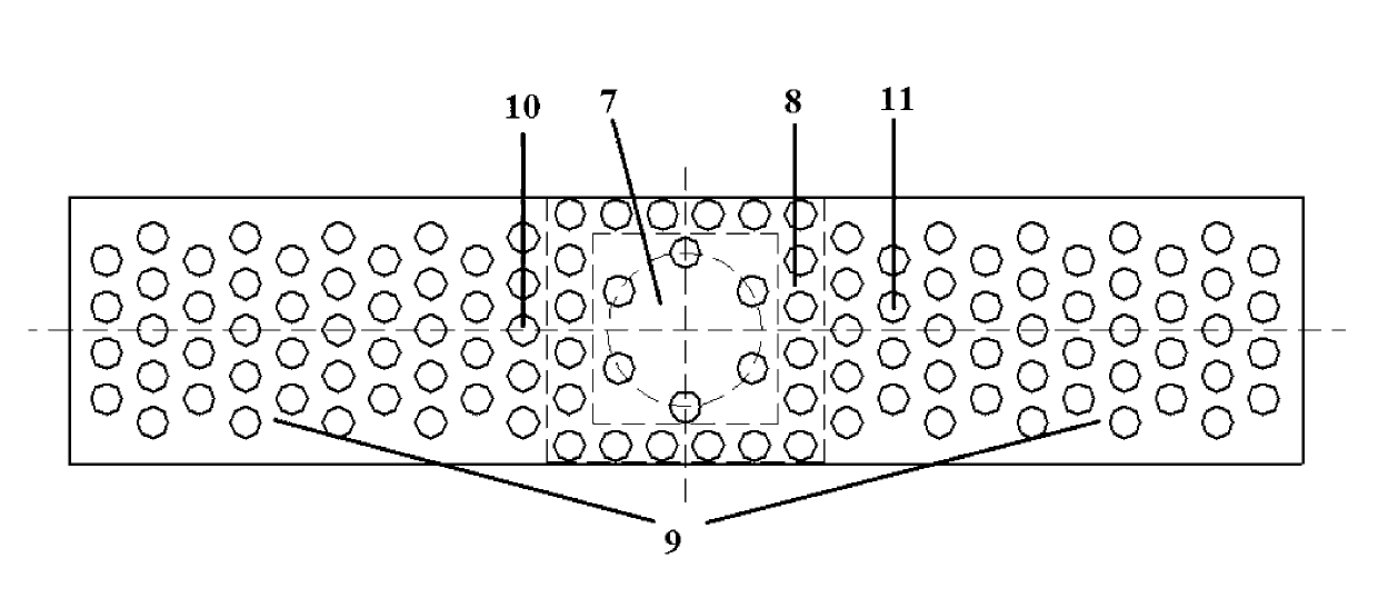
[0019] Such as figure 2 and image 3 As shown, a plurality of through holes are distributed on the baffle plate 3, the diameter of the through holes is 1 / 5 of the diameter of the inlet pipe 1, and the distance between the horizontal and vertical holes is 1 / 2 of the diameter of the through holes. The arrangem...


PUM


Abstract

The invention discloses a head baffle of a plate-fin heat exchanger. A head comprises a fluid inlet tube and an arc head. A baffle is disposed in the middle of arc structure of the arc head. 1-3mm of thickness of the baffle is recommended. The baffle is provided with a plurality of through holes. The diameter of each through hole is one fifth of that of the inlet tube. Spacing of both transverse and longitudinal holes is half of the hole diameter. The through holes arrayed on the baffle include three feature regions, namely an inlet tube projection region, a projection peripheral region and a bilateral symmetry region. The baffle structure is provided according to the logistical distribution feature of the traditional head. The diameter of the through holes is defined. The head baffle is simple and practical. Logistical distribution condition inside the head is improved effectively. The structural parameters of the baffle are defined according to the structural size of the head, so that the head baffle is universal, can be used as design basis and is important to improving heat exchange performance of the plate-fin heat exchanger.

Description

Technical field: [0001] The invention relates to a baffle suitable for the head of a plate-fin heat exchanger, which belongs to the technical field of material flow distribution optimization and heat transfer enhancement of the plate-fin heat exchanger, especially through the adjustment of the position of the baffle, the thickness of the baffle and the opening of the hole Through the optimization analysis of the hole diameter, a universally applicable baffle plate structure for the head of the plate-fin heat exchanger is obtained. Background technique: [0002] The main factor causing the uneven material distribution of the plate-fin heat exchanger is the unreasonable head structure. The size of the outlet channel of the traditional head and the position of the outlet channel relative to the inlet pipe have an important impact on the material distribution of the head. For the improvement of the head structure, there are two ideas: the secondary head and the installation of p...

Claims


Application Information

Patent Timeline
Patent Type & Authority Applications(China)
IPC IPC(8): F28F9/22
Inventor 王武昌李玉星季鹏朱建鲁胡其会
Owner CHINA UNIV OF PETROLEUM (EAST CHINA)
Why Eureka
Try Eureka