
Electric lifting wire pole

A utility pole and electric technology, which is applied in the field of power transmission and transformation, can solve the problems of insufficient mechanical strength, bulky utility poles, and insufficient impact strength, etc., and achieve excellent impact resistance and insulation performance, high resource recovery rate, and simple and light structure Effect

Inactive Publication Date: 2013-04-03
XINYANG POWER SUPPLY OF HENAN ELECTRIC POWER CORP
View PDF3 Cites 10 Cited by
  • Summary
  • Abstract
  • Description
  • Claims
  • Application Information

AI Technical Summary

Problems solved by technology

[0002] Most of the electric poles in the prior art are cement prefabricated one-piece pole bodies. This kind of electric poles are extremely heavy and high in height. When erecting lines and installing ancillary equipment, operators must climb up to work, resulting in a risk factor for the operation. Large and low work efficiency, which seriously restricts the work efficiency of transmission line erection. At the same time, large lifting equipment and a lot of manpower and material resources are needed in the installation process of utility poles. At the same time, traditional utility poles have poor corrosion resistance and impact resistance, and their service life is relatively long. Short, and resource recycling rate is low, which also increases the operating cost of power supply lines
[0003] At present, there are few other types of multi-level electric poles, but although they are more convenient in transportation and installation, they still cannot effectively avoid the problem of operators working at heights, and although this kind of electric poles are light, their mechanical strength is not enough. Especially the impact strength is not enough, easy to damage

Method used


Image

  • Electric lifting wire pole

Examples


Embodiment Construction

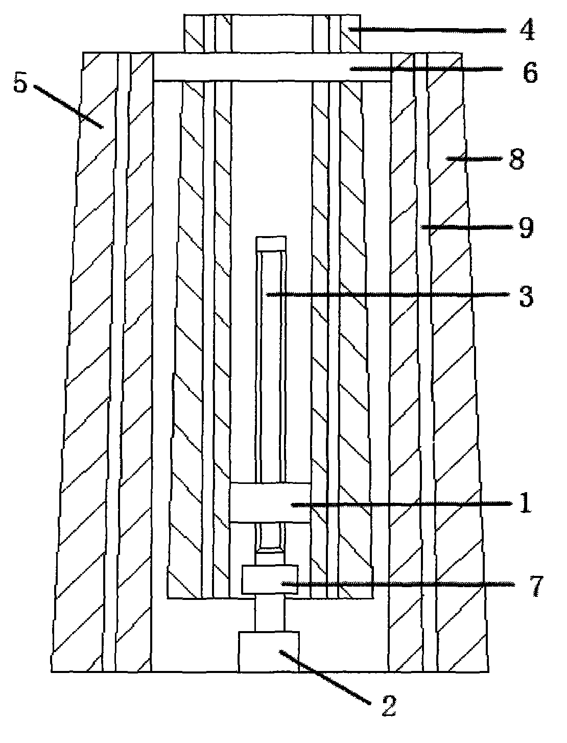
[0014] Such as figure 1 As shown, an electric lifting utility pole includes a utility pole body. The utility pole body is composed of at least two utility pole bodies, a threaded transmission sleeve 1, a driving motor 2 and a lead screw 3. One of the utility pole body A utility pole body is nested inside another utility pole body, a positioning block 6 is set between the inner utility pole body 4 and the outer utility pole body 5, and the inner wall of the threaded transmission sleeve 1 is provided with a smooth threaded outer wall and is aligned with the inner wall of the utility pole. Reliable connection, the drive motor 3 is reliably connected to the foundation of the utility pole body and connected to the lead screw 3 through the coupling 7, the lead screw 3 is reliably connected to the threaded transmission sleeve 1 and threaded, and the utility pole body is composed of the base material 8 and the The steel reinforcement rib 9 is formed, and the steel reinforcement rib 9 ...


PUM


Abstract

The invention discloses an electric lifting wire pole. The electric lifting wire pole comprises a wire pole body, wherein the wire pole body comprises at least two wire pole bodies, a thread transmission sleeve, a driving motor and a lead screw, one of the wire rod bodies is nested inside the other one, a positioning block is arranged between the wire pole body at the inner layer and the wire pole body at the outer layer, a thread is arranged at the inner wall of the thread transmission sleeve, the outer wall of the thread transmission sleeve is smooth and reliably connected with the inner walls of the wire pole bodies, the driving motor is reliably connected with the foundation of the wire pole bodies and connected with the lead screw by a coupler, and the lead screw is reliably connected with the thread transmission sleeve and is in thread transmission. The electric lifting wire pole is made of hard light type insulating material reinforcing bars, combined by the plurality of pole bodies and lifted by transmission via the lead screw. The electric lifting wire pole has the advantages of being free and convenient in height adjustment, simple and portable in structure, excellent in corrosion resistance, impact resistance and insulating property, wide in usage range, long in service life, and higher in resource recovery rate.

Description

technical field [0001] The invention relates to an electric lifting pole, which belongs to the field of power transmission and transformation. Background technique [0002] Most of the electric poles in the prior art are cement prefabricated one-piece pole bodies. This kind of electric poles are extremely heavy and high in height. When erecting lines and installing ancillary equipment, operators must climb up to work, resulting in a risk factor for the operation. Large and low work efficiency, which seriously restricts the work efficiency of transmission line erection. At the same time, large lifting equipment and a lot of manpower and material resources are needed in the installation process of utility poles. At the same time, traditional utility poles have poor corrosion resistance and impact resistance, and their service life is relatively long. Short, and resource recycling rate is low, which also increases the operating cost of power supply lines. [0003] At present, ...

Claims


Application Information

Patent Timeline
IPC IPC(8): E04H12/18E04H12/02
Inventor 孙建超王玲
Owner XINYANG POWER SUPPLY OF HENAN ELECTRIC POWER CORP
Learn More