
Moving load analog loading method and device for rail transit wheel axle

A technology for moving loads and rail transit, applied in tracks, track maintenance, roads, etc., can solve the problems of inability to achieve uniform movement of wheel and axle loads, size limitations, and difficulty in control, achieve reliable and convenient loading platforms, reduce size, and avoid long distances. The effect of the acceleration section

Inactive Publication Date: 2013-04-03
ZHEJIANG UNIV
View PDF0 Cites 27 Cited by
  • Summary
  • Abstract
  • Description
  • Claims
  • Application Information

AI Technical Summary

Problems solved by technology

The indoor model test is limited by the size of the site and the speed of the vehicle, and it is difficult to realize the high-speed mobile loading of the real vehicle; although the real wheel axle movement process can be used for the on-site in-situ test, the environment is complex and difficult to control, and the repeatability is poor
Existing wheel shaft dynamic load simulation devices, such as the frequency-adjustable amplitude modulation SBZ30 dynamic exciter, use the rapid rotation of the eccentric block to generate vertical excitation force, which can realize high-frequency excitation at a fixed position. The disadvantage is that the wheel shaft cannot be realized. Mobility of loads; the test system for simulating the effect of high-speed traffic moving loads uses a forward and reverse moving loader controlled by a centrifugal rotating motor to drive a vertical vibrator to realize the moving loading of the wheel axle load, but due to size limitations, it is impossible to realize the wheel axle load mobility. The load moves at a constant speed at a higher speed

Method used


Image

  • Moving load analog loading method and device for rail transit wheel axle
  • Moving load analog loading method and device for rail transit wheel axle
  • Moving load analog loading method and device for rail transit wheel axle

Examples


Embodiment Construction

[0025] The present invention will be further described below in conjunction with drawings and embodiments.

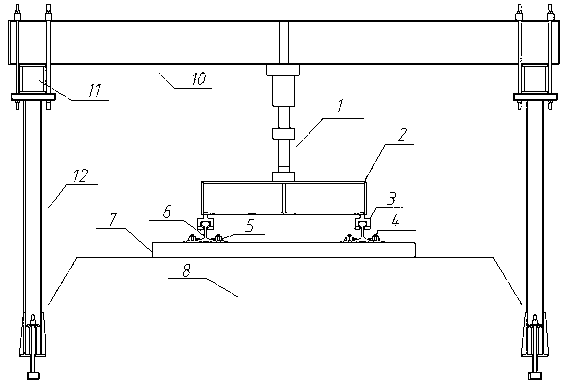
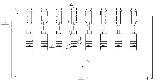
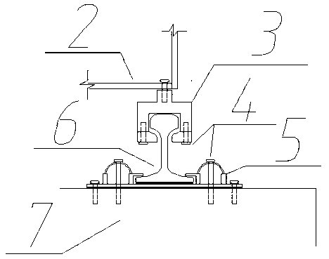
[0026] This example is in figure 1 with figure 2 The moving load simulation loading device of the rail transit axle shown in the figure is carried out on the ballasted track structure, the fastener system 5 is WJ-7 type, the rail 6 type is CHN60, the sleeper 7 is III type reinforced concrete sleeper, and the ballast bed 8 is divided into the surface layer of the ballast bed and the bottom layer of the ballast bed, the surface layer of the ballast bed is made of graded gravel, the bottom layer of the ballast bed is made of A / B filler, and the distance between each sleeper 7 along the track direction is , a total of 8 sleepers 7 are arranged, and 8 actuators 1 are arranged above the position of each sleeper 7. The bottom of each actuator 1 is connected at the mid-span of the distribution beam 2 with a high-strength bolt 4, and the bottom of the distribution beam 2 two ...


PUM


Abstract

The invention discloses a moving load analog loading method and device for a rail transit wheel axle. A plurality of actuators are distributed above sleepers along a rail direction, the bottom of each actuator is connected in the span middle of a distribution girder, the bottoms of two ends of the distribution girder are arranged above steel rails at two sides, two continuous steel rails are laid on the sleepers and are respectively cut into mutually independent sectional steel rails above the positions of the sleepers, and each pair of sectional steel rail and sleeper is connected by a fastening system. Vertical pressure and upward pulling force are applied on the actuators by an anti-drop external member. A stress load time travel curve of a single fastening system under the effect of the wheel axle moving at different moving speeds is determined according to a train-rail-roadbed theoretical model and is used as a load exciting curve of each actuator, and the adjacent actuators are dynamically excited sequentially in the same time interval along the moving direction of the wheel axle so as to realize the analog loading of the moving load of the wheel axle at different speeds. The invention provides a reliable and convenient loading platform for developing a rail traffic dynamic model test research.

Description

technical field [0001] The invention relates to a load loading method and device, in particular to a method and device for simulating the moving load of rail transit axles. Background technique [0002] Our country is in the stage of rapid development of rail transportation, whether it is intercity ordinary railway and high-speed railway, or urban subway and light rail, all are in the process of rapid construction. With the construction and operation of rail transit facilities, more and more engineering problems have emerged. When the train passes at high speed, the load is transmitted to the offline structure through the interaction between the wheel axle and the rail. Compared with the traditional fixed-point cyclic loading, the interaction between the wheel axle and the rail has a typical movement effect and speed effect. Each structural layer experiences the same loading process along the traveling direction of the train. This kind of force bearing mode, which is diffe...

Claims


Application Information

Patent Timeline
IPC IPC(8): E01B35/12
CPCG06F17/5009E01B35/12G06F30/20
Inventor 边学成蒋红光徐翔陈仁朋陈云敏蒋建群程翀金皖锋
Owner ZHEJIANG UNIV
Learn More