
A self-aligning fixture for clamping precision forgings

A precision forging and clamping technology, applied in the field of self-aligning fixtures for clamping precision forgings, can solve the problems of low cost of use, poor clamping of forgings, poor precision, etc. long life effect

Active Publication Date: 2017-02-08
LUOYANG LUOLING BEARING SCI & TECH
View PDF6 Cites 0 Cited by
  • Summary
  • Abstract
  • Description
  • Claims
  • Application Information

AI Technical Summary

Problems solved by technology

[0005] The above three types of fixtures have their own advantages and disadvantages. Self-aligning hard jaw fixtures have good centering performance, durability and safety, but the positioning pins are difficult to process. It is difficult, and the most prominent shortcoming is poor precision. The power chuck is connected with the head of the lathe through three screws. The body makes corresponding follow-up, and at the same time, the moving claw that cooperates with the star-shaped wedge body as a wedge-shaped gap is limited in its axial direction, so it can only move in the radial direction; the clamping claw is screwed into the compound arc of the replacement claw In the groove, and in the proper position, the positioning pin is tightly matched with the replacement claw. After the chuck claw is assembled, install the three chuck claws on the appropriate positions of the three moving claws of the chuck with screws respectively. The movement of the chuck The tooth distance between the claw and the tooth rack of the replacement claw is 1.5mm, and the tooth distance of the moving claw for the D320 chuck is 2.5mm, that is, the adjustment step is 1.5mm or 2.5mm. The claws can better clamp the inner diameter of the bearing ring, and the runout of the outer circle of the clamped bearing ring can reach a certain level, but precision forgings cannot be processed safely with this fixture, and with the intensification of industry competition, the number of precision forgings used More and more, the machining allowance of forgings is getting smaller and smaller, it is inevitable to overcome the shortage of this kind of fixture
[0006] As for the inner-expanding spring clamp, this clamp is designed to clamp the inner diameter surface of the turned workpiece. It has the advantages of firm clamping, safety, good durability, and easy use. However, this clamp is only an expedient method for clamping the inner diameter of precision forgings. , because it is not self-aligning, it cannot be clamped for thin-walled precision forgings, and because of its limited expansion and contraction, it cannot be used for forgings with large deviations in inner diameter. "
[0007] The inner diameter fixture of the round soft jaw of the car, because the chuck jaws use screws to connect the three chuck jaws to the three moving jaws of the power chuck, because the chuck connected to it is universal, so the scope of application of this fixture Large, low cost of use, and the biggest defect is that it can't adjust the center. It reproduces the roundness defect of the forging. Secondly, because the workpiece clamping surface is smooth, the clamping of the forging is not firm, and it is easy to cause the processing of the outer circle. The vertical difference is not good, so this kind of fixture can only clamp parts with a large wall thickness coefficient, and this fixture cannot be used for parts with thin walls
[0008] To sum up, the existing commonly used internal expansion fixtures cannot better meet the lathing clamping of precision forgings and forgings with small machining allowances, especially the clamping lathing of thin-walled forgings.

Method used


Image

  • A self-aligning fixture for clamping precision forgings
  • A self-aligning fixture for clamping precision forgings
  • A self-aligning fixture for clamping precision forgings

Examples


Embodiment Construction

[0031] The present invention can be explained in more detail by the following examples, and the present invention is not limited to the following examples;

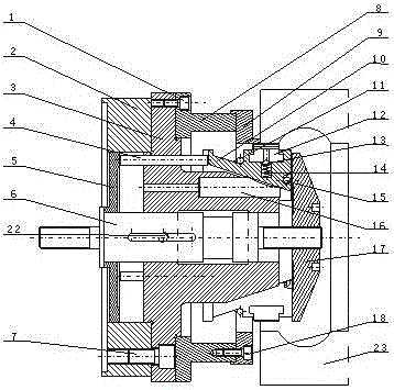
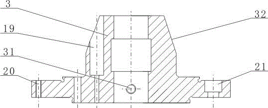
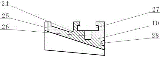
[0032] combined with Figure 1~4 The self-aligning fixture for clamping precision forgings includes a transition plate 2, a frame body 3, a transmission mechanism and a clamping mechanism. A plurality of through thread holes 20 and stepped holes 21 are arranged. The thread holes 20 and the stepped holes 21 are arranged alternately. A plurality of through pin holes are arranged at the end surface near the annular boss. On the outside of the seat frame body 3 There is an anti-rotation pin installation hole 31 penetrating to the middle inner hole on the edge surface, wherein one end of the frame body 3 is connected to the transition plate 2 by at least two fastening screws B7, and the other end of the frame body 3 is connected by the fastening screw A1 Connect the positioning ring base 8, the end of the positioning ring bas...


PUM


Abstract

The invention relates to a centering clamp for clamping a precision forged piece, relating to the field of machining. According to the invention, a centering claw is arranged at an end part of a seat frame body, is simultaneously provided with a clamping claw and is driven by a pull rod to move left and right so as to clamp a workpiece tightly, and furthermore, an automatic centering effect is achieved by the reasonable rotation of the centering claw and a centering pin together in a pin hole of the seat frame body. According to the invention, the clamping claw is convenient to detach, accurate in positioning, large in expansion / contraction quantity, and capable of clamping precision and rough forged pieces, meanwhile, the clamping precision of the clamp can be guaranteed because the jitter of the seat frame body of the clamp is measurable and controllable when the seat frame body is connected to a machine tool, and the centering clamp has the characteristics of compact structure, equal-division property and firmness for clamping, strong centering capacity, high clamping precision, convenience for regulation, simplicity for replacement of quick-wear parts, long service life and the like, is greatly reduced in use cost during actual production, and is suitable for large-range popularization and application.

Description

[0001] 【Technical field】 [0002] The invention relates to the field of mechanical processing, in particular to an aligning fixture, in particular to an aligning fixture for clamping precision forgings. [0003] 【Background technique】 [0004] It is known that the blank of the bearing ring is a precision forging. When machining a bearing ring with an outer diameter of φ62~φ300 on a lathe, in order to meet the requirements of multi-specification, large-volume, high-efficiency, and high-quality processing, the on-turn machining process The clamps used in the bearing put forward very high requirements. At present, the internal expansion clamping clamps commonly used in the bearing industry basically include: self-aligning hard jaw clamps, internal expansion spring clamps and self-car round soft jaw clamps. [0005] The above three types of fixtures have their own advantages and disadvantages. Self-aligning hard jaw fixtures have good centering performance, durability and safety, b...

Claims


Application Information

Patent Timeline
Patent Type & Authority Patents(China)
IPC IPC(8): B23Q3/12
Inventor 苗俊惠祖朝余马志杰
Owner LUOYANG LUOLING BEARING SCI & TECH
Learn More