Tooth alignment clamp for ultra-long rack and positioning machining method for tooth alignment thereof

A processing method and rack technology, which are applied in metal processing equipment, gear tooth manufacturing devices, gear teeth, etc., can solve the problem that the ultra-long rack cannot be directly processed, the processing of the ultra-long rack is difficult, and the pitch accuracy is not easy to guarantee, etc. problems, to achieve the effect of reducing processing and manufacturing costs, saving processing time, and simple structure

Inactive Publication Date: 2013-04-03
MCC SFRE HEAVY IND EQUIP
View PDF3 Cites 10 Cited by
  • Summary
  • Abstract
  • Description
  • Claims
  • Application Information

AI Technical Summary

Problems solved by technology

[0004] The purpose of the present invention is to provide an ultra-long rack-to-tooth jig, which solves the problem that the existing technology cannot directly process ultra-long racks, and can only process them segment by segment, and then integrate them. The problem
[0005] Another object of the present invention is to provide a tooth alignment processing method for processing ultra-long racks on a gear shaping machine, which solves the difficulty in processing ultra-long racks and requires multi-stage docking of the screw holes and positioning pin holes to improve work efficiency. Low cost, high production cost, and difficult to guarantee the pitch accuracy after docking

Method used


Image

  • Tooth alignment clamp for ultra-long rack and positioning machining method for tooth alignment thereof
  • Tooth alignment clamp for ultra-long rack and positioning machining method for tooth alignment thereof
  • Tooth alignment clamp for ultra-long rack and positioning machining method for tooth alignment thereof

Examples


Embodiment Construction

[0021] The present invention will be described in detail below with reference to the drawings and specific embodiments.

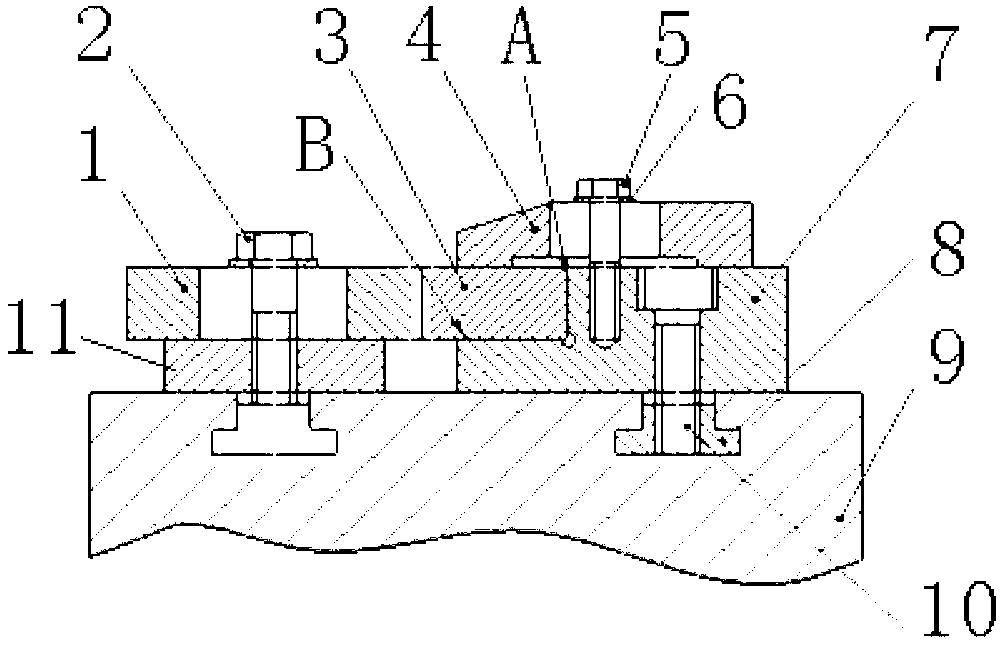
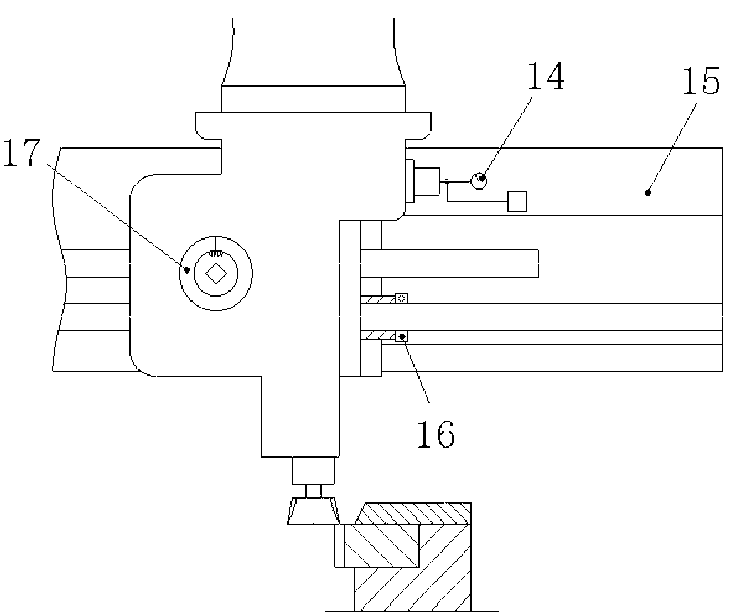
[0022] Reference figure 1 , figure 2 , Is a schematic diagram of the structure of the ultra-long rack-to-tooth fixture of the present invention (when the teeth are in the working state), including two parallel inverted T-slots longitudinally arranged on the table surface of the rack machine table 9, each inverted T An inverted T-shaped fixed block 8 is provided in the groove, and a positioning seat 11 and a clamping body 7 are respectively arranged on the upper edges of the two inverted T-shaped grooves; the positioning seat 11 is provided with a counter tooth block 1, the positioning seat 11 and the counter The tooth block 1 is fixedly connected by the hexagon socket screw 12. In addition, the tooth block 1, the positioning seat 11, and the corresponding lower inverted T-shaped fixed block 8 are connected together by the clamping bolt 2; the clamping body 7 i...


PUM


Abstract

The invention discloses a tooth alignment clamp for an ultra-long rack. The tooth alignment clamp comprises two parallel inverted T-shaped slots which are arranged vertically on a workbench of a rack machining machine, an inverted T-shaped fixing block is arranged in every inverted T-shaped slot, and the upper edges of the two inverted T-shaped slots are respectively provided with a positioning seat and a clamp body; tooth alignment blocks are arranged on the positioning seats; and the clamp bodies are fixedly connected with the other inverted T-shaped fixing block under the corresponding clamp body and are provided with a step with the same height as the tooth alignment blocks in a position facing the tooth alignment blocks, and the steps are used for arrangement of a toothed blank to be machined, and a pressure plate is arranged on the upper surface of the toothed blank. The invention also discloses a positioning machining method for tooth alignment during machining of the ultra-long rack on a gear shaping machine, and positioning machining for tooth alignment of the ultra-long rack is completed through a plurality of steps. The structure of the device is simple, the process of the method is also simple, assembly and disassembly can be performed conveniently, and the pitch and the cumulative pitch error can be ensured for teeth cut later only by ensuring that the positions of the teeth of the rack are not changed relative to the workbench.

Description

Technical field [0001] The invention belongs to the technical field of mechanical equipment manufacturing, and specifically relates to an ultra-long rack gear-to-tooth fixture. The invention also relates to a tooth-aligning processing method for processing an ultra-long rack on a gear shaper. Background technique [0002] In the existing Y51150 gear shaping machine processing racks, due to the limitation of the length of the accessory table, only racks within 2000mm in length can be processed. In fact, sometimes the rack lengths that need to be processed often exceed 2000mm. Therefore, for ultra-long rack processing, the traditional processing method is to calculate according to the drawings, and then divide the rack into multiple segments of racks below 2000mm for processing separately, and add a screw hole and positioning at the segment The pin hole is solved by multi-stage butting. This processing method not only requires calculation and drawing according to the drawings in a...

Claims


Application Information

Patent Timeline
IPC IPC(8): B23F23/06B23F5/12
Inventor 陈政权初静静
Owner MCC SFRE HEAVY IND EQUIP
Why Eureka
Try Eureka