
Quick change device for female die

A technology of concave molds and mold bases, which is applied in metal processing equipment, forming tools, manufacturing tools, etc., can solve the problems of low universality of mold bases, high cost of opening molds, cumbersome and time-consuming operations, affecting experiments, and production efficiency. The effect of facilitating multi-process stamping operations, overcoming installation gaps, and shortening die change time

Inactive Publication Date: 2013-04-03
FUJIAN UNIV OF TECH
View PDF2 Cites 3 Cited by
  • Summary
  • Abstract
  • Description
  • Claims
  • Application Information

AI Technical Summary

Problems solved by technology

[0002] In the serialization of various sizes of rotary parts using dies, such as deep drawing, bulging, turning holes, etc., especially in the multi-process forming test, the die and punch must be replaced between processes. Before replacing the concave-convex die, the entire mold must be disassembled from the press. The traditional concave-convex die is fixed by locking the screws between the fixed plate and the mold frame to achieve positioning. When replacing the concave-convex die, the fixed plate and the mold frame need to be separated. , and some even need to replace the mold base. These operations are cumbersome and time-consuming, which affects the experiment and production efficiency, and the mold base is not versatile, resulting in the cost of multiple molds.

Method used


Image

  • Quick change device for female die
  • Quick change device for female die
  • Quick change device for female die

Examples


Embodiment Construction

[0018] In order to describe the technical content, structural features, achieved goals and effects of the present invention in detail, the following will be described in detail in conjunction with the embodiments and accompanying drawings.

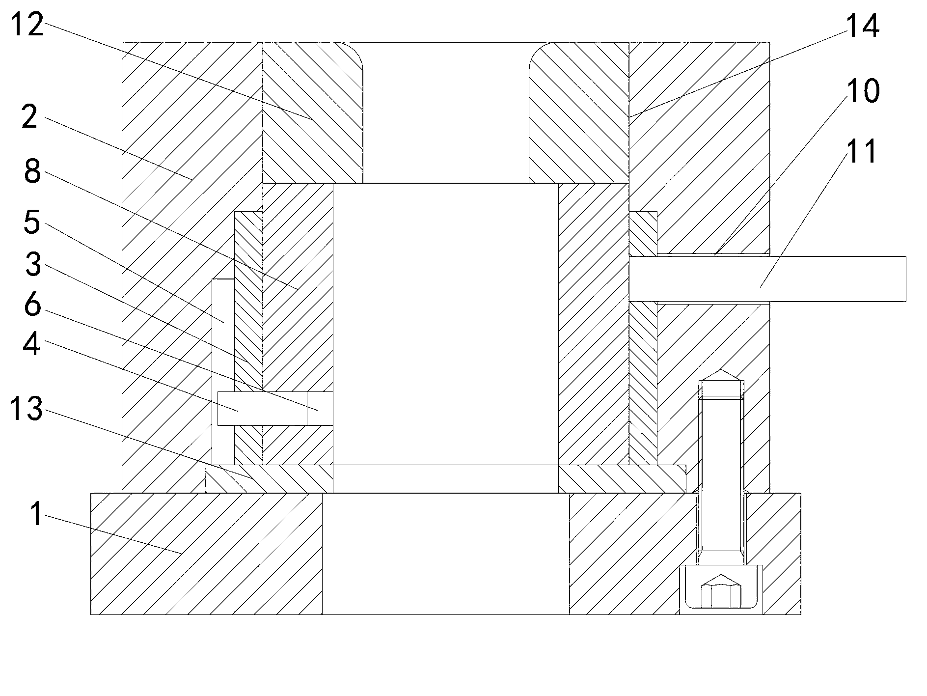
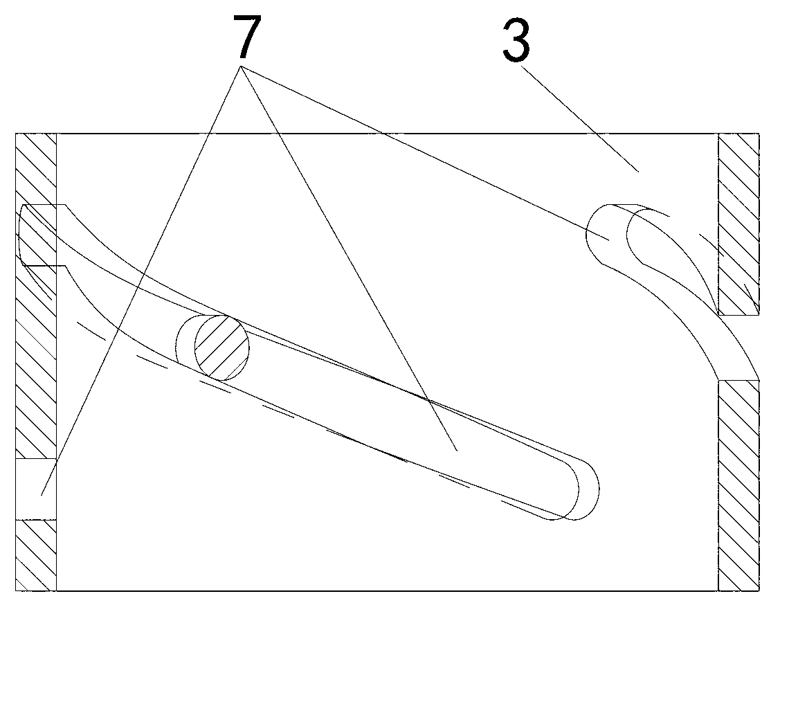
[0019] See 1 and figure 2 , the solution of this embodiment is: a die quick change device, mainly composed of a die base 1, a die holder 2, a die 12 and a die pad 8, the die holder 2 is a hollow cylindrical tube body and is fixed on the die base 1, the die 12 and the die pad 8 are arranged inside the die holder 2, the die 12 is supported by the die pad 8, and the die pad 8 There is also a spiral sleeve 3 between the inner wall of the die holder 2, and the wall of the spiral sleeve 3 is provided with a track groove 7 and a socket 9, and a pin hole 6 is provided on the wall of the die pad 8, A handle slot 10 and a sliding pin limiting groove 5 are provided on the wall of the die holder 2, and the track groove 7, the pin hole 6 and the slid...


PUM


Abstract

The invention discloses a quick change device for a female die. The quick change device mainly comprises a die holder, a female die fixing seat, the female die and a female die cushion, wherein a spiral sleeve is further arranged between the female die cushion and the inner wall of the female die fixing seat, a track groove and an insertion hole are formed in the cylinder wall of the spiral sleeve, a pin hole is formed in the wall of the female die cushion, a handle slot and a sliding pin position-limiting groove are formed in the wall of the female die fixing seat, the track groove, the pin hole and the sliding pin position-limiting groove are connected through a sliding pin, and a handle penetrates the handle slot and is arranged into the insertion hole. The quick change device disclosed by the invention has the beneficial effects that the female die cushion can directly eject the female die out of the female die fixing seat by rotating the spiral sleeve through the handle, so that the die change time is greatly shortened; and simultaneously, the die change action does not involve the position relation between the female die fixing seat and other blanking parts, so as to overcome a larger mounting gap required for the common quick change structure, realize the same precise positioning with the fixed female die, eliminate the need of re-aligning the positions of an upper die and a lower die after die change and greatly facilitate multi-step stamping operation.

Description

technical field [0001] The invention relates to a die quick change device for a punching die, in particular to a die quick change device for a die. Background technique [0002] In the serialization of various sizes of rotary parts using dies, such as deep drawing, bulging, turning holes, etc., especially in the multi-process forming test, the die and punch must be replaced between processes. Before replacing the concave-convex mold, the whole set of mold must be disassembled from the press. The traditional concave-convex mold is fixed by screw locking between the fixed plate and the mold frame to achieve positioning. When replacing the concave-convex mold, the fixed plate and the mold frame need to be separated. , Some even need to replace the mold base, these operations are cumbersome and time-consuming, affecting the experiment and production efficiency, and the mold base is not versatile, resulting in the cost of multiple molds. Contents of the invention [0003] The ...

Claims


Application Information

Patent Timeline
IPC IPC(8): B21D37/04B21D37/10
Inventor 陈胤林涵王火生翁黎清杨明阳罗裕民
Owner FUJIAN UNIV OF TECH
Learn More