Rectifier circuit device
A technology of rectification circuit and AC voltage, applied in the direction of output power conversion device, electrical components, high-efficiency power electronic conversion, etc., can solve problems such as circuit loss
- Summary
- Abstract
- Description
- Claims
- Application Information
AI Technical Summary
Problems solved by technology
Method used
Image

Examples
Embodiment approach 1
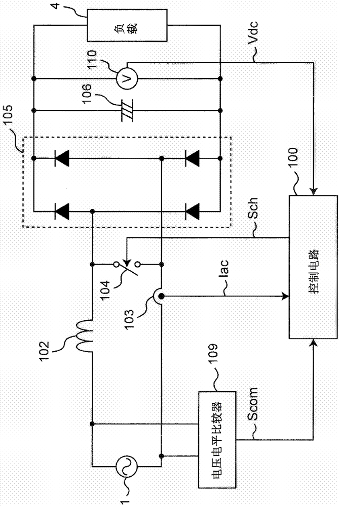
[0155] figure 1 It is a circuit diagram showing the configuration of the rectifier circuit device according to Embodiment 1 of the present invention.
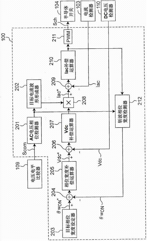
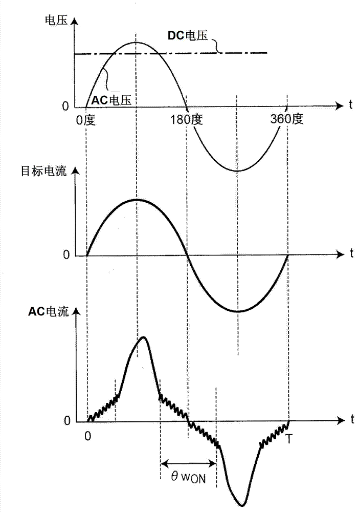
[0156] exist figure 1 In this case, one circuit is formed by short-circuiting two output terminals of a single-phase AC power supply 1 with a semiconductor switch 104 via a reactor 102 . The current detector 103 detects the current of this circuit, and outputs a signal indicating the detected current value Iac to the control circuit 100 . If the semiconductor switch 104 is turned on, the current of the reactor 102 increases. On the other hand, if the semiconductor switch 104 is turned off, the current flowing through the reactor 102 is rectified in the diode bridge 105, and the rectified current flows smoothly. The capacitor 106 and the load 4 drive the load 4 . The DC voltage Vdc across the smoothing capacitor 106 applied to the load 4 is detected by the DC voltage detector 110 , and the DC voltage detector 110 outputs a ...
Embodiment approach 2
[0169] In Embodiment 1, the phase width θw for chopping is detected ON , adjust the DC voltage command Vdc * , and Embodiment 2 is characterized in that the phase width (hereinafter referred to as "chopping stop phase width") θw of the chopping stop state is detected OFF , by adjusting the DC voltage command Vdc, the same effect can be obtained.
[0170] Figure 4A It is a diagram for explaining the control operation of the third operation example of the control circuit 100 of the rectifier circuit device according to Embodiment 2 of the present invention, and shows the relationship between the AC voltage and the rectified DC voltage, the target current waveform to be controlled, and the actual Signal waveform diagram of the controlled AC current. in addition, Figure 4B It is a diagram for explaining the control operation of the fourth operation example of the control circuit 100 of the rectifier circuit device according to Embodiment 2 of the present invention, and shows...
Embodiment approach 3
[0175] The feature of the third embodiment is that the control method of the first embodiment is simplified, and the chopping phase width detector 212 detects a period in which the polarity (sign) of the AC voltage in the chopping stop state does not change and is fixed from 0 degrees or 180 degrees. Phase width θ1w of the first half of (positive interval or negative interval) ON , to perform the chopping control.
[0176] Figure 5A It is a diagram for explaining the control operation of the fifth operation example of the control circuit 100 of the rectifier circuit device according to Embodiment 3 of the present invention, and shows the relationship between the AC voltage and the rectified DC voltage, the target current waveform to be controlled, and the actual Signal waveform diagram of the controlled AC current. in addition, Figure 5B It is a diagram for explaining the control operation of the sixth operation example of the control circuit 100 of the rectifier circuit ...
PUM
 Abstract
Description
Claims
Application Information
 - R&D
- Intellectual Property
- Life Sciences
- Materials
- Tech Scout
- Unparalleled Data Quality
- Higher Quality Content
- 60% Fewer Hallucinations
Browse by: Latest US Patents, China's latest patents, Technical Efficacy Thesaurus, Application Domain, Technology Topic, Popular Technical Reports.
© 2025 PatSnap. All rights reserved.Legal|Privacy policy|Modern Slavery Act Transparency Statement|Sitemap|About US| Contact US: help@patsnap.com