Wire crimping terminal

A crimping terminal and wire crimping technology, which is applied in the direction of conductive connection, connection, multi-core cable end parts, etc., can solve the problem of heating at the front of the crimping terminal, achieve enhanced mechanical connection strength, low processing cost, and easy processing Easy to produce effects

Inactive Publication Date: 2013-03-27
TYCO ELECTRONICS (SHANGHAI) CO LTD
View PDF5 Cites 2 Cited by
  • Summary
  • Abstract
  • Description
  • Claims
  • Application Information

AI Technical Summary

Problems solved by technology

[0010] One of the objects of the present invention is to provide a crimping terminal that can solve the above-mentioned big problem of heating at the front of the crimping terminal

Method used


Image

  • Wire crimping terminal
  • Wire crimping terminal
  • Wire crimping terminal

Examples


Embodiment Construction

[0043] Various embodiments of the invention will be described below with reference to the accompanying drawings, which form a part hereof. It should be understood that although directional terms, such as "front," "rear," "upper," "lower," etc., are used herein to describe various exemplary structural parts and elements of the invention, these Terminology is for explanatory purposes only, based on the example orientations shown in the figures. Since the disclosed embodiments of the present invention may be arranged in different orientations, these directional terms are for illustration only and should not be viewed as limiting. Where possible, the same or similar reference numerals used in the present invention refer to the same components.

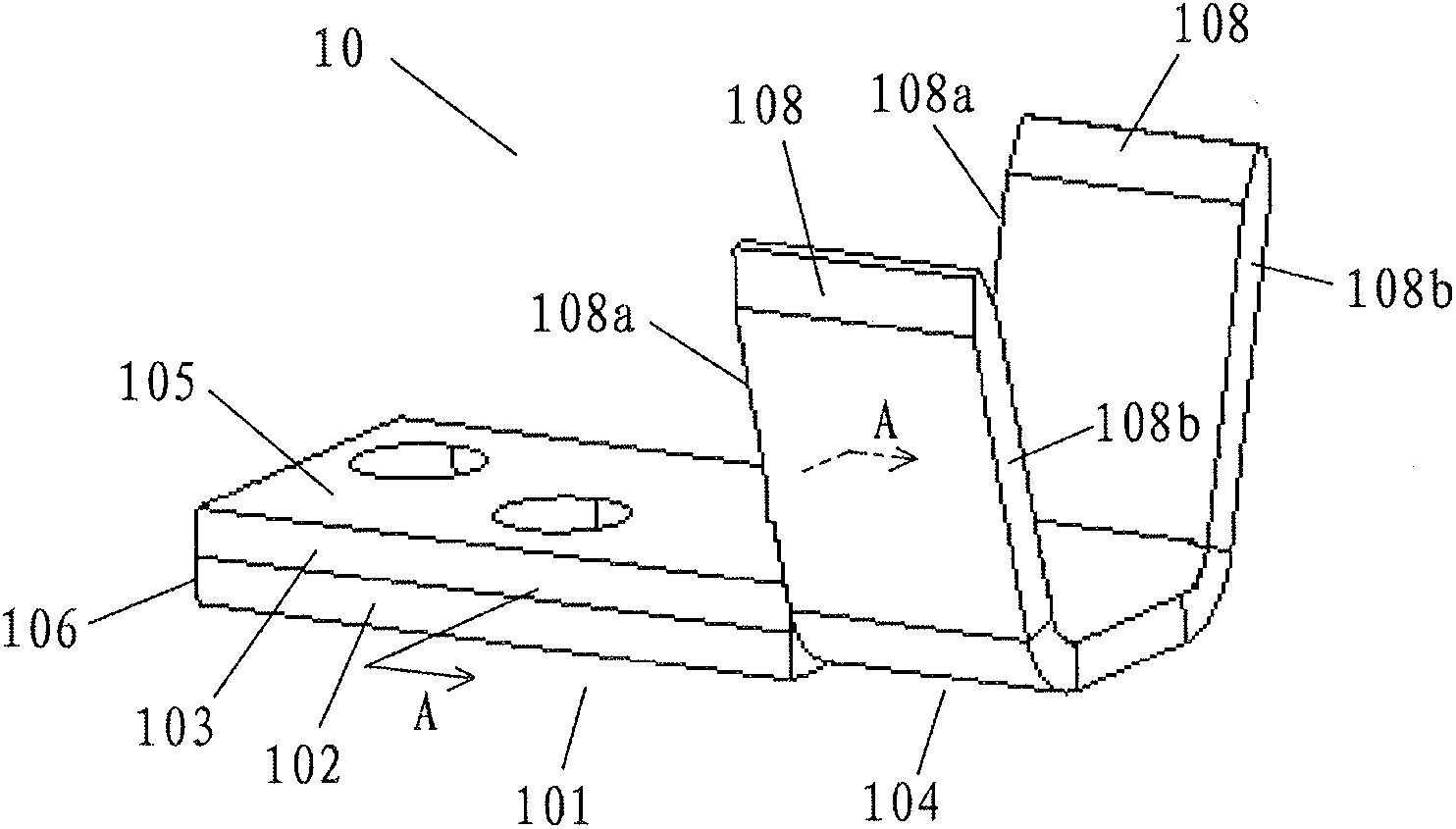
[0044] Figure 2a A crimp terminal 10 according to a specific embodiment of the present invention is shown. The crimping terminal is made of conductive material, such as metal material. Such as Figure 2a As shown, the crimping termin...


PUM


Abstract

The invention relates to a wire crimping terminal which comprises a crimping terminal body made of conducting material. The crimping terminal body comprises a first-layer crimping terminal and a second-layer crimping terminal which are attached to each other. Wing parts which extend from two opposite sides of the rear portion of the crimping terminal body are used for crimping wires to the rear portion of the crimping terminal body. Each wing part comprises a front end and a rear end. The first-layer crimping terminal and the second layer crimping terminal coincide and extend at least from the front ends of the wing parts. By the wire crimping terminal, the problem that the front portion of the crimping terminal generates excessive heat is solved, and mechanical connection strength of a wire crimping area and a transition area of the crimping terminal is enhanced.

Description

technical field [0001] The invention relates to a wire crimping terminal, in particular to a crimping terminal suitable for large current. Background technique [0002] Wire crimp terminals are often used to connect two contacts in a circuit loop. In use, the rear end of the wire crimping terminal is generally used to crimp the wire from one contact point in the circuit loop, and the other end is used to connect another contact point in the circuit loop. [0003] figure 1 A structure of an existing wire crimp terminal is shown. Such as figure 1 As shown, the crimp terminal comprises a crimp terminal body 2 having a front part 3 and a rear part 4 . At the rear portion 4 of the crimp terminal there is provided a wire crimping area 5 and wings 6 extending from opposite sides of the wire crimping area 5 . When using this crimping terminal, the wire is placed in the wire crimping area 5, and then the wings 6 are deformed to press the wire placed in the wire crimping area 5, ...

Claims


Application Information

Patent Timeline
IPC IPC(8): H01R11/11H01R4/18
CPCH01R11/11H01R4/184
Inventor 周啸
Owner TYCO ELECTRONICS (SHANGHAI) CO LTD
Why Eureka
Try Eureka