Motor control device and image forming apparatus

A technology of motor control and motor control unit, applied in the direction of motor control, motor generator control, electric controller, etc., can solve the problem of stopping the driven object, and achieve the effect of high-speed stop and suppression of saturation

Active Publication Date: 2013-03-27
BROTHER KOGYO KK
View PDF10 Cites 8 Cited by
  • Summary
  • Abstract
  • Description
  • Claims
  • Application Information

AI Technical Summary

Problems solved by technology

However, switch control is a simple control method, and thus it is difficult to stop the driven object at a target position at high speed by this control method

Method used


Image

  • Motor control device and image forming apparatus
  • Motor control device and image forming apparatus
  • Motor control device and image forming apparatus

Examples


Embodiment Construction

[0034] Hereinafter, illustrative embodiments of the present disclosure will be described with reference to the accompanying drawings.

[0035] [First illustrative embodiment]

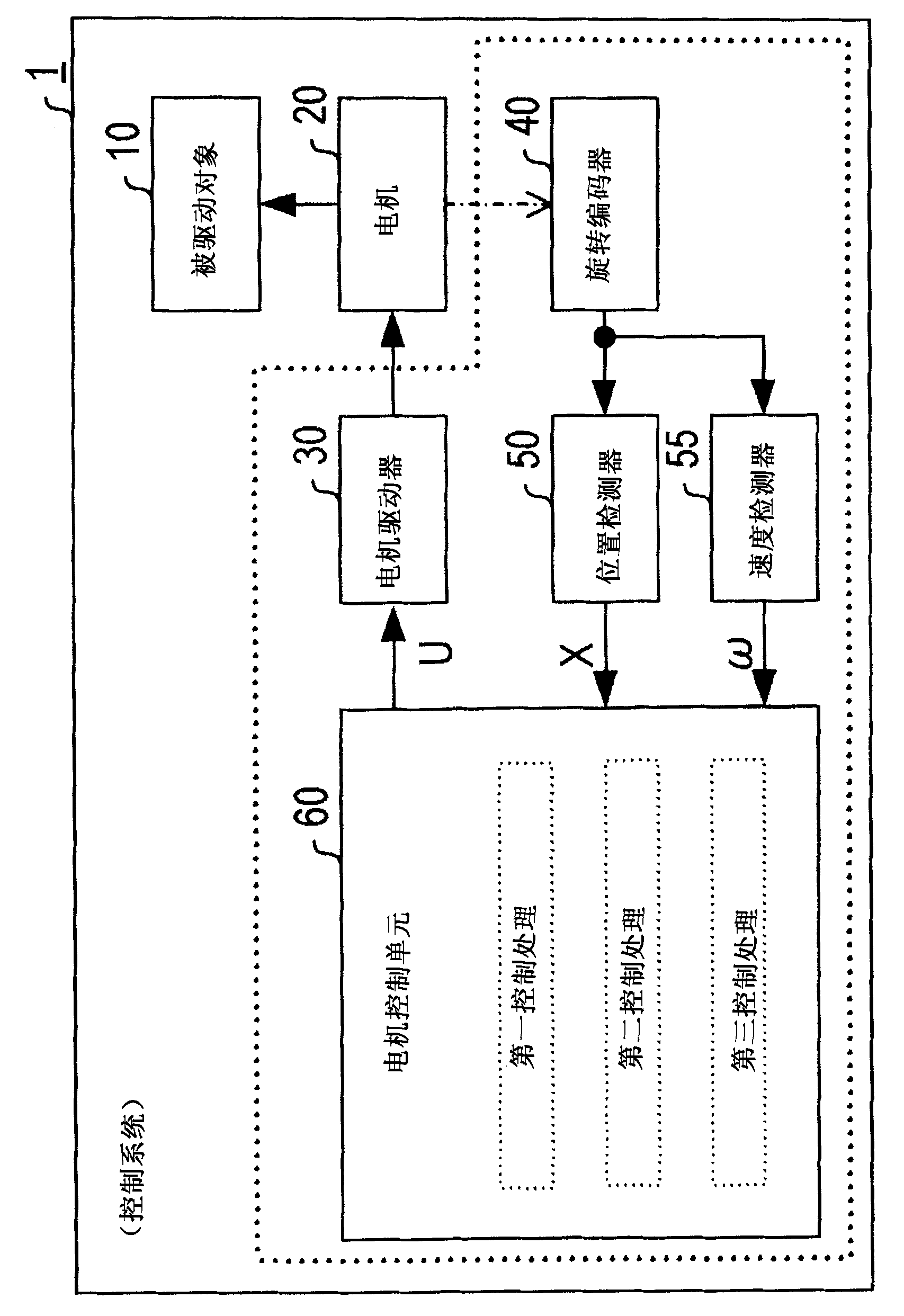
[0036] Such as figure 1As shown in , the control system 1 of this illustrative embodiment includes: a motor (DC motor) 20 for driving a driven object 10, a motor driver 30, a rotary encoder 40 connected to the rotary shaft of the motor 20, a The output signal of the rotary encoder 40 detects the position detector 50 of the rotational position X of the motor, the speed detector 55 detects the rotational speed ω of the motor 20 based on the output signal of the rotary encoder 40, and calculates The motor control unit 60 operates the current command value U of the amount.

[0037] This control system 1 is integrated in an electric device such as an image forming device, and performs motor control according to commands input from a main control unit (such as a main microcomputer) of the electric device. ...


PUM


Abstract

A motor control device comprises: a motor control unit; and a signal output unit, wherein the motor control unit controls a motor based on an output signal of the signal output unit, wherein the motor control unit is configured to function as: a first control unit performs a first motor control, in which a current upper limit is estimated based on a rotation speed of the motor and is input to the motor, a second control unit performs a second motor control, in which a second driving current, which is a driving current lower than the first driving current at the end of the first motor control is input, a third control unit performs a third motor control, in which a third driving current to be input to the motor is determined, and a switching unit that sequentially switches the first, second, and third control units.

Description

[0001] Cross References to Related Applications [0002] This application claims priority from Japanese Patent Application No. 2011-203502 filed on September 16, 2011, the entire subject matter of which is hereby incorporated by reference. technical field [0003] The present disclosure relates to a motor control device and an image forming apparatus. Background technique [0004] As a technique for transferring a driven object to a target position at high speed, bang-bang control is known (for example, see JP-A-2007-086904 and JP-A-H07-302121). [0005] Switch control is advantageous in driving a driven object at high speed. However, switch control is a simple control method, and thus it is difficult to stop a driven object at a target position at high speed by this control method. Meanwhile, as a technique for stopping a driven object at a target position at high speed, feedback control based on target distribution (target trajectory) is known. Contents of the inventio...

Claims


Application Information

Patent Timeline
IPC IPC(8): G05B19/416H02P7/00G05D3/12B41J2/01B41J23/00H02P3/00H02P29/00
CPCG05B19/19B41J29/38G05B2219/42215G05B11/01G05B2219/45187B41J11/42
Inventor 家崎健一
Owner BROTHER KOGYO KK
Why Eureka
Try Eureka