
Reconstruction method and imaging device of three-dimensional profiles of object surfaces

A technology for surface and three-dimensional contours of objects, applied in measuring devices, optical devices, instruments, etc., can solve the problems of data acquisition occupying CCD resources, increasing system complexity and cost, white light source fluorescence band interference, etc., and achieve contour reconstruction accuracy High, accurate fluorescence molecular tomography images and short reconstruction times

Inactive Publication Date: 2013-03-27
TSINGHUA UNIV
View PDF1 Cites 14 Cited by
  • Summary
  • Abstract
  • Description
  • Claims
  • Application Information

AI Technical Summary

Problems solved by technology

[0003] At present, the existing technology solves the problem of object surface contour reconstruction in fluorescence molecular tomography, such as the back projection reconstruction method under white light, which has the advantage that it can basically achieve the contour accuracy required by the fluorescence molecular tomography method, but the imaging accuracy is not high. The light source still interferes with the fluorescence band to a certain extent, and data acquisition takes up CCD resources; the contour extraction method based on Gray-coded structured light has the advantage of achieving high resolution through calibration, but for objects at the same angle, reconstruction requires much Frame Gray coded images is very time-consuming, and the device for switching patterns will greatly increase the complexity and cost of the system, so the effect is not ideal

Method used


Image

  • Reconstruction method and imaging device of three-dimensional profiles of object surfaces
  • Reconstruction method and imaging device of three-dimensional profiles of object surfaces
  • Reconstruction method and imaging device of three-dimensional profiles of object surfaces

Examples


Embodiment Construction

[0018] The present invention will be described in detail below in conjunction with the accompanying drawings and embodiments.

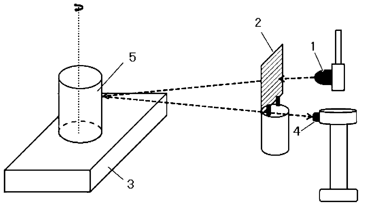
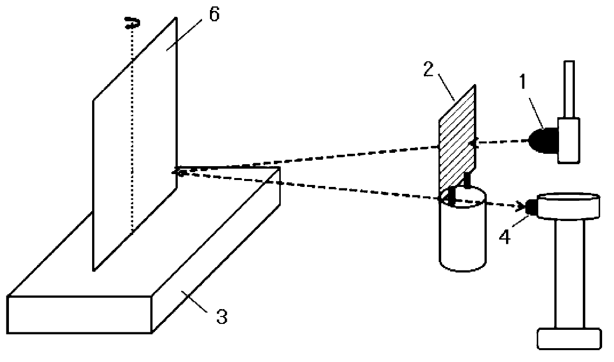
[0019] Such as figure 1 As shown, the object surface three-dimensional profile imaging device of the present invention includes a light emitting diode 1, a grating 2, a rotary table 3, a camera 4, a controller and a computer (not shown in the figure); The axis is connected to the controller, and the controller makes the rotating table 3 realize a 360° rotation by controlling the rotating shaft. Photograph all the fringes on the surface of the object to be imaged, and send the fringe images of the object to be imaged to the computer.

[0020] Such as figure 1 As shown, in the above-mentioned embodiment, the object to be imaged can be the object to be measured 5, and the center of the object to be measured 5 passes through the extension line of the rotation axis of the rotary table 3 (such as figure 1 shown by the thin dotted line in ).

[0021] Suc...


PUM

PropertyMeasurementUnit
Wavelengthaaaaaaaaaa
Grating constantaaaaaaaaaa

Abstract

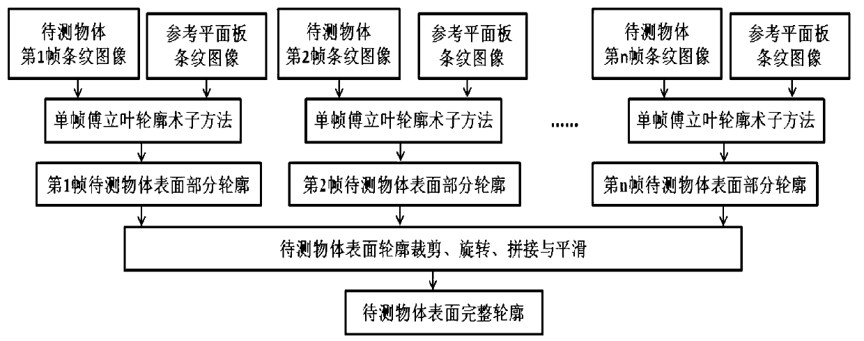
The invention relates to a reconstruction method and an imaging device of three-dimensional profiles of object surfaces. The reconstruction method includes that a reference plane plate is placed on a rotary table, light emitted by a luminous diode is projected to the surface of the reference plane plate to form a plurality of stripes through gratings, and a camera shoots the stripes of the reference plane plate and sends the stripes to a computer; an object to be tested is placed on the rotary table, the light emitted by the luminous diode is projected to the surface of the reference plane plate to form the plurality of the stripes through gratings, the camera shoots the stripes of the reference plane plate and sends the stripes to the computer; a controller controls the rotary table to rotate, and the camera shoots n frames of stripe images of the object to be tested in a range of 360 degrees; the computer obtains partial profiles of the surface of the object to be tested at n different angles through a single frame Fourier transform profilometry method; and a complete profile of the object to be tested is obtained by synthesizing the partial profiles of the surface of the object to be tested at all angles. The reconstruction method and the imaging device of three-dimensional profiles of object surfaces can be widely applied to three-dimensional profile reconstruction of object surfaces of fluorescence molecular tomography.

Description

technical field [0001] The invention relates to an object surface reconstruction method and an imaging device, in particular to an object surface three-dimensional contour reconstruction method and an imaging device suitable for fluorescent molecular tomography imaging. Background technique [0002] Fluorescence molecular tomography has become an important method for life medical research, which is helpful for early disease diagnosis, especially cancer diagnosis and localization, and effectively promotes the development of drugs and the analysis of life mechanisms. Fluorescence molecular tomography methods can be mainly divided into finite element-based methods and radiation transfer equation-based methods. Regardless of the reconstruction method, it is necessary to predict the boundary fluorescence data in the forward problem, and then update it in the inversion problem. Optical parameter values ​​for the model to minimize the difference between boundary measurements and fo...

Claims


Application Information

Patent Timeline
IPC IPC(8): G01B11/25
Inventor 白净石璧尔张宾刘飞
Owner TSINGHUA UNIV
Learn More