
Water-electricity hybrid power cooling tower

A hybrid power and cooling tower technology, which is applied in the field of cooling towers, can solve the problems of rising cooling water temperature in cooling towers, insufficient power of water turbines, and inability to increase power of water turbines, etc., achieving obvious effects of ensuring safe production and energy-saving transformation

Inactive Publication Date: 2013-03-27
张育仁
View PDF5 Cites 12 Cited by
  • Summary
  • Abstract
  • Description
  • Claims
  • Application Information

AI Technical Summary

Problems solved by technology

[0002] The rotation of the water turbine in the cooling tower is driven by the water flow, which in turn drives the fan to work. The degree of cooling treatment of the cooling water by the cooling tower is closely related to the speed of the fan. Generally, the power of the water turbine is limited by the flow rate and the size of the water head. It is impossible to further increase the power of the turbine
When the water flow rate or water head entering the water turbine is too small, so that the power of the water turbine is insufficient, and the speed of the fan cannot meet the cooling requirements, the temperature of the cooling water in the cooling tower will also continue to rise, which will affect the working efficiency of the cooling tower. is unfavorable

Method used


Image

  • Water-electricity hybrid power cooling tower
  • Water-electricity hybrid power cooling tower
  • Water-electricity hybrid power cooling tower

Examples


Embodiment 1

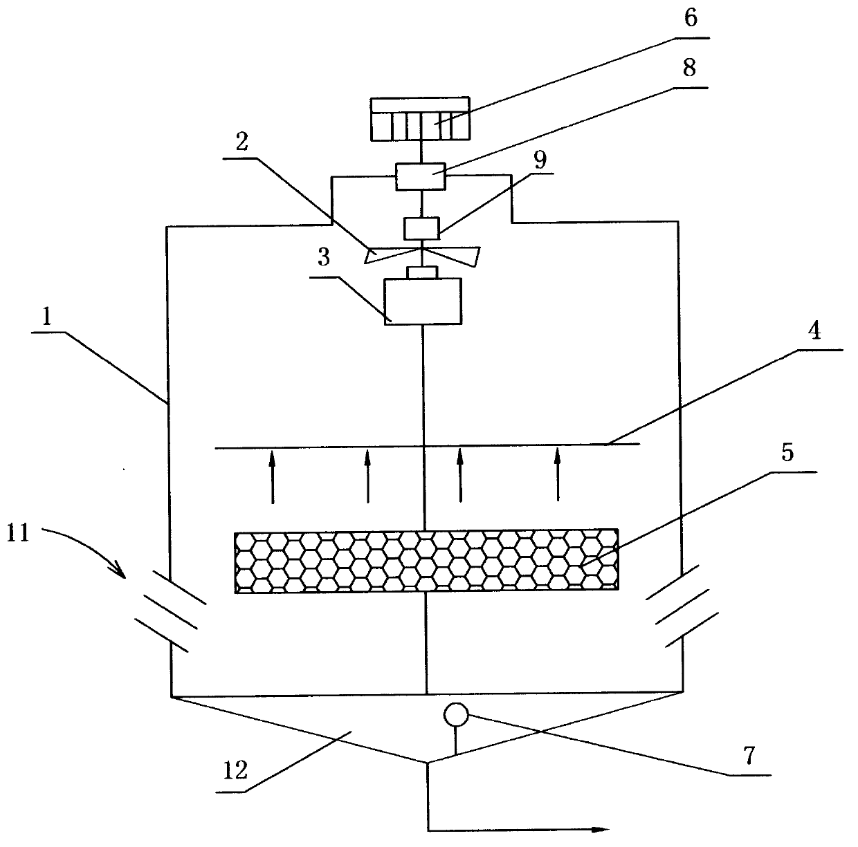
[0027] Example 1: see figure 1 , a hydroelectric hybrid cooling tower, which has: a tower body 1 surrounded by a shell, with a cold water outlet at the bottom; a fan installed on the top of the tower body and used to discharge hot and humid air inside the tower body 2. A water turbine 3 connected to the fan through the power output shaft, which is arranged on the upper part of the inner cavity of the tower body. The impeller in the water turbine is driven by the water flow of the water inlet pipe, and the impeller and the power output shaft of the water turbine are connected to each other in one body; a device The water distributor 4 in the inner cavity of the tower and the heat dissipation material 5 located under the water distributor and used for heat exchange between water and air. Common heat dissipation materials in this field are fillers, such as S-wave fillers, stepped trapezoidal ramp fillers, Point wave packing, two-way wave packing, oblique fold wave packing, obliqu...

Embodiment 2

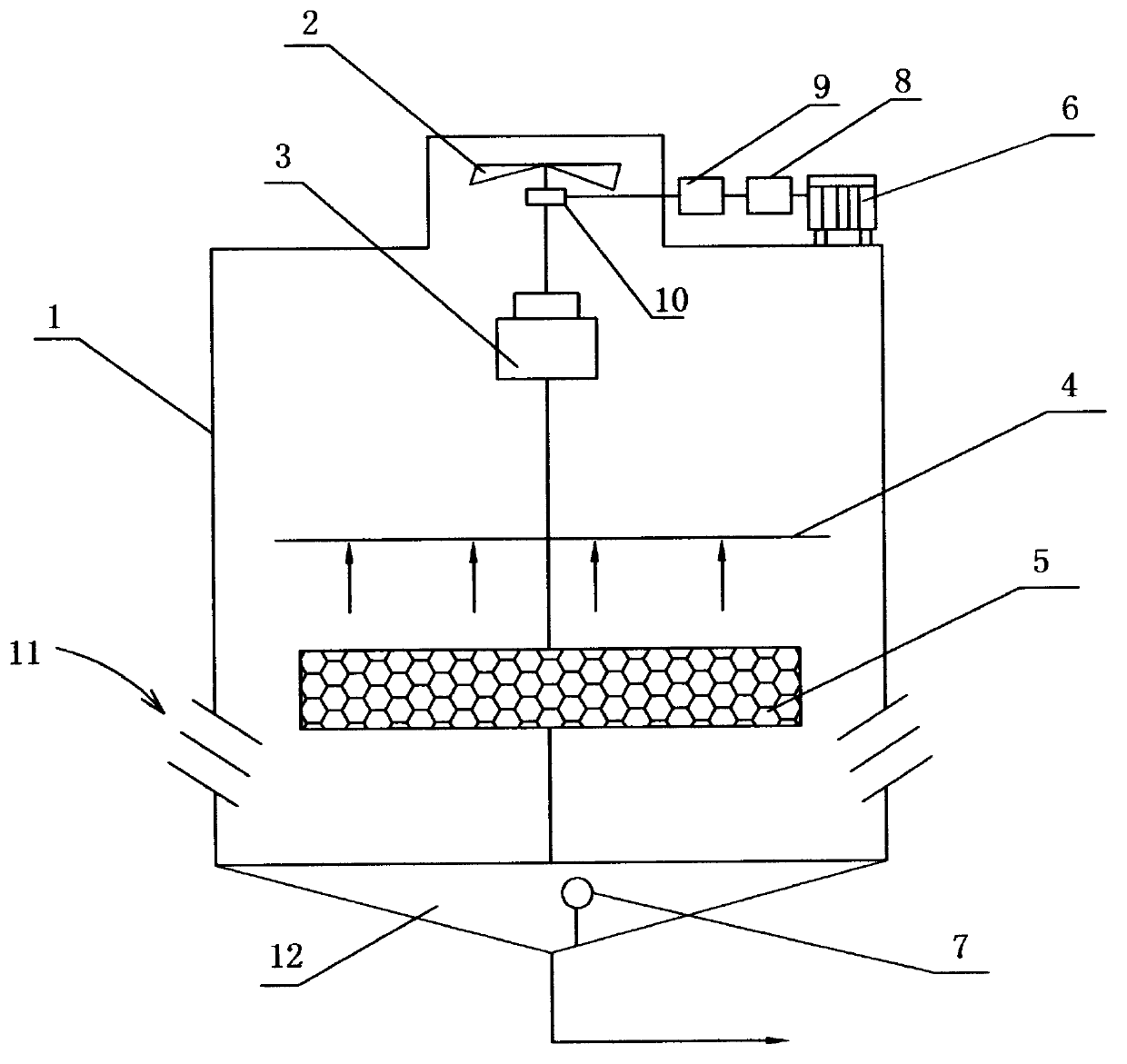
[0030] Example 2: see figure 2 , a transmission mechanism of a hydroelectric hybrid cooling tower includes: a transmission horizontally arranged, an automatic clutch, a hybrid power box, a transmission 8, which is connected between the motor and the automatic clutch; an automatic clutch 9, which is connected between the transmission and the power hybrid Between the boxes 10; a hybrid box 10, which is located between the automatic clutch, the output shaft of the water turbine and the power input shaft of the fan. Other structures of this case are the same as Embodiment 1, and are not described in detail here.

[0031] The hybrid power box rotates through the gears, so that the two powers of water energy and electric energy are superimposed, and the speed is increased to improve the cooling capacity of the cooling tower.

Embodiment 3

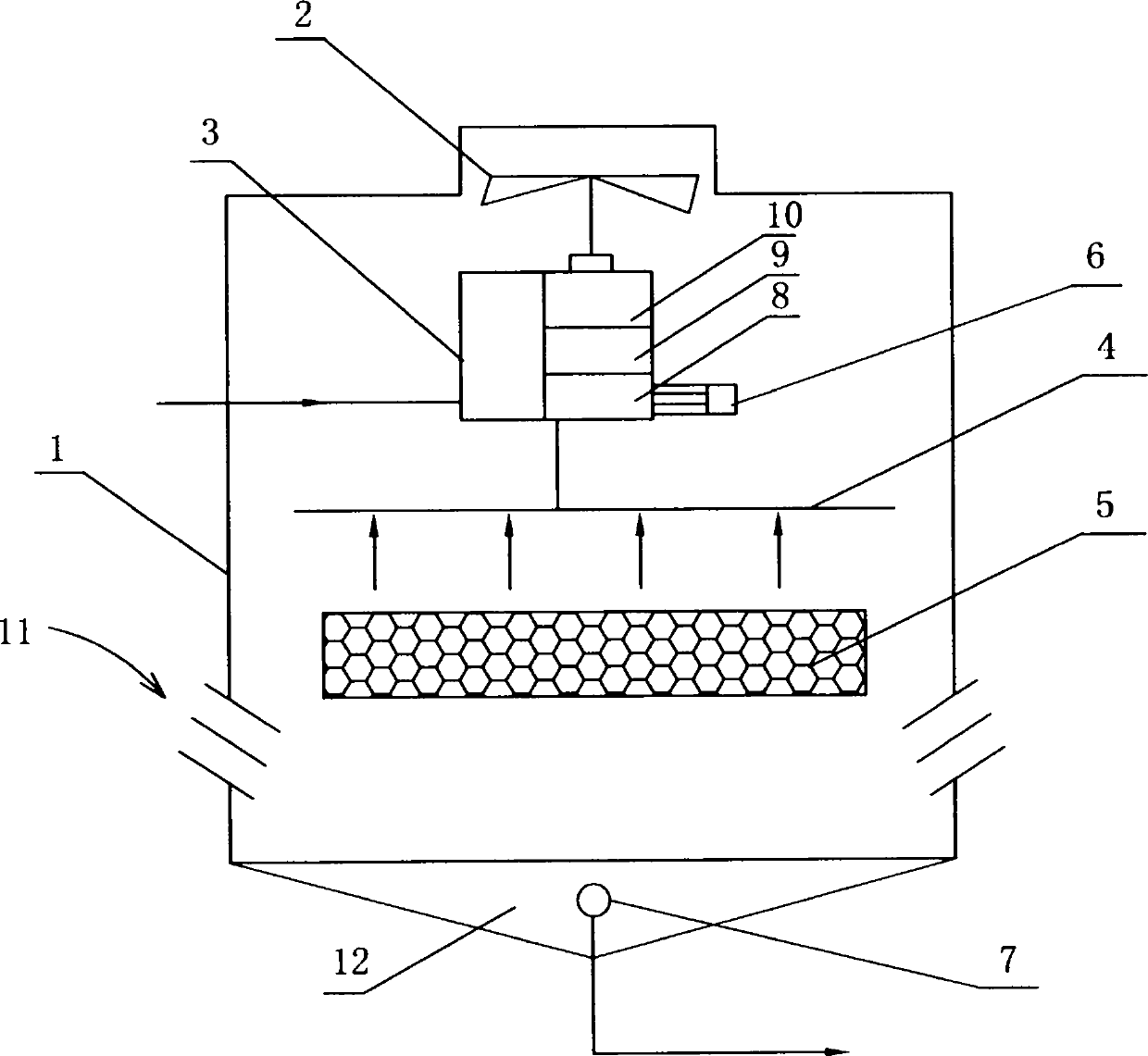
[0032] Example 3, see image 3 A transmission mechanism of a hydroelectric hybrid cooling tower includes: a transmission, an automatic clutch, a hybrid power box, a transmission 8, which is connected between the motor and the automatic clutch; an automatic clutch 9, which is connected between the transmission and the power mixing box 10 ; Hybrid box 10, which is located between the automatic clutch, the power output shaft of the water turbine and the power output shaft of the blower fan, the power unit and the transmission mechanism adopt an integrated structure in this case. The other structures of this case are the same as those in Embodiment 1, and will not be described in detail here.

[0033] The description of known technologies, such as transmission, automatic clutch, hybrid power box structure and its detailed assembly scheme, etc., is omitted herein.


PUM


Abstract

The invention discloses a water-electricity hybrid power cooling tower. The water-electricity hybrid power cooling tower is provided with a tower body, a fan, a water turbine, a water distributor, heat dissipation materials, a motor, a transmission mechanism, a temperature sensor and a control chip circuit board, wherein the tower body is formed by the enclosing of a shell; the fan is arranged at the top of the tower body and is used for discharging damp and hot air in the tower body; the water turbine is connected with the fan by a power output shaft and is arranged at the upper part of an inner cavity of the tower body; the water distributor is arranged in an inner cavity of the tower body, the heat dissipation materials are arranged below the water distributor and are used for heat exchange of water and air; the transmission mechanism is arranged between the motor and the power output shaft of the water turbine; the temperature sensor is arranged in a collecting tank of the tower body; and the control chip circuit board is electrically connected with the temperature sensor and the motor. The water-electricity hybrid power cooling tower has the beneficial effects that the change condition of the water temperature of the cooling tower can be detected automatically, and when the water temperature exceeds a preset value, the motor is started and driven and has a resultant force with the water turbine so as to drive to the fan to rotate, and the input power of the fan is increased, so that the temperature reducing capability of the cooling tower is improved, and the water temperature is kept in a set temperature range.

Description

technical field [0001] The invention relates to the technical field of cooling towers, in particular to a hydroelectric hybrid cooling tower. Background technique [0002] The rotation of the water turbine in the cooling tower is driven by the water flow, which in turn drives the fan to work. The degree of cooling treatment of the cooling water by the cooling tower is closely related to the speed of the fan. Generally, the power of the water turbine is limited by the flow rate and the size of the water head. It is impossible to further increase the power of the water turbine. When the water flow rate or water head entering the water turbine is too small, so that the power of the water turbine is insufficient, and the speed of the fan cannot meet the cooling requirements, the temperature of the cooling water in the cooling tower will also continue to rise, which will affect the working efficiency of the cooling tower. is unfavorable. Contents of the invention [0003] The...

Claims


Application Information

Patent Timeline
Patent Type & Authority Applications(China)
IPC IPC(8): F28C1/00F28F27/02
CPCF28F27/02F28C1/00Y02B30/70
Inventor 张育仁
Owner 张育仁
Learn More