RCS (reinforced concrete structure) combined node with continuous webs and partially-cut flanges

A technology of partial cutting and continuous web, applied in the direction of construction, building structure, etc., can solve the problems of difficult concrete pouring, affecting the construction progress, construction difficulties, etc., to save the formwork and its support, improve the construction efficiency, and reduce the self-weight. Effect

Inactive Publication Date: 2013-03-27
XI'AN UNIVERSITY OF ARCHITECTURE AND TECHNOLOGY
View PDF10 Cites 9 Cited by
  • Summary
  • Abstract
  • Description
  • Claims
  • Application Information

AI Technical Summary

Problems solved by technology

Analysis of the reasons is mainly due to the fact that the current RCS composite joints either adopt the steel beam penetration method, that is, the steel beam continuously passes through the reinforced concrete column. Since the flange area of ​​the steel beam at this joint is relatively large, the longitudinal reinforcement in the column must be effectively transmitted. It is necessary to perforate the flange, which makes the construction difficult; moreover, the larger flange will also cause difficulties in pouring concrete, which will also affect the construction progress; or the column penetration method, that is, the longitudinal reinforcement of the reinforced concrete column penetrates through the node , the steel beams are connected on both sides of the joint by taking appropriate measures (welding or bolted connections). Since the steel beams of this joint are discontinuous, it is easy to cause sudden failure of the weld or sudden failure of the bolts, which are not ideal ductile failures.

Method used


Image

  • RCS (reinforced concrete structure) combined node with continuous webs and partially-cut flanges
  • RCS (reinforced concrete structure) combined node with continuous webs and partially-cut flanges
  • RCS (reinforced concrete structure) combined node with continuous webs and partially-cut flanges

Examples


Embodiment Construction

[0028] The present invention will be further described below in conjunction with specific examples and accompanying drawings.

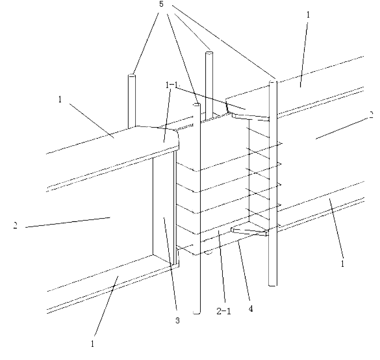
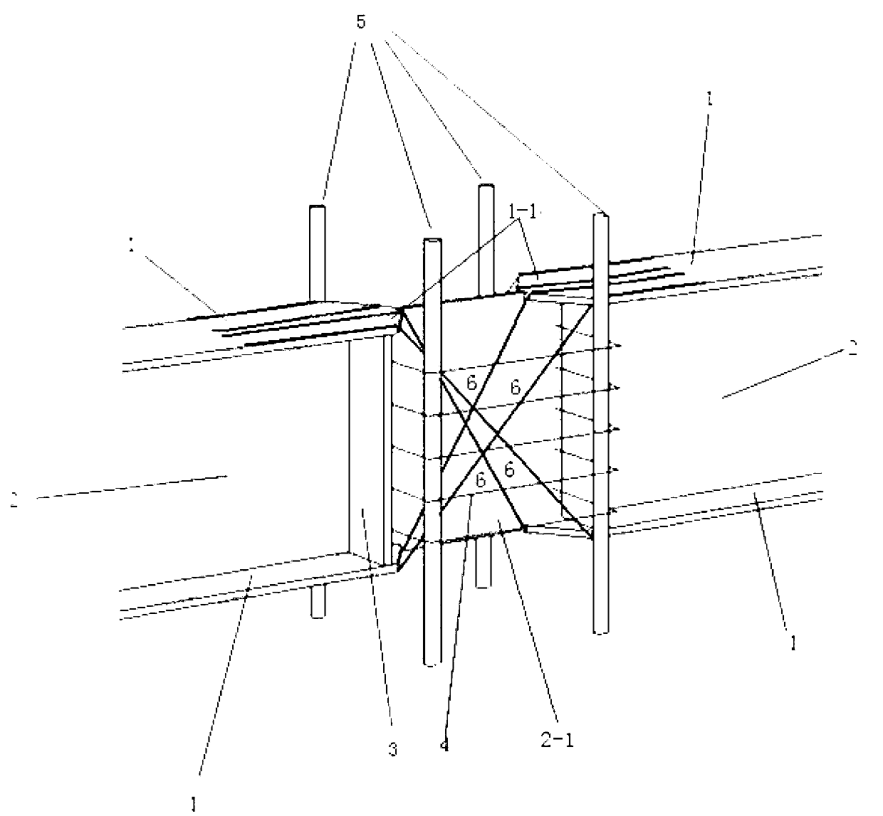
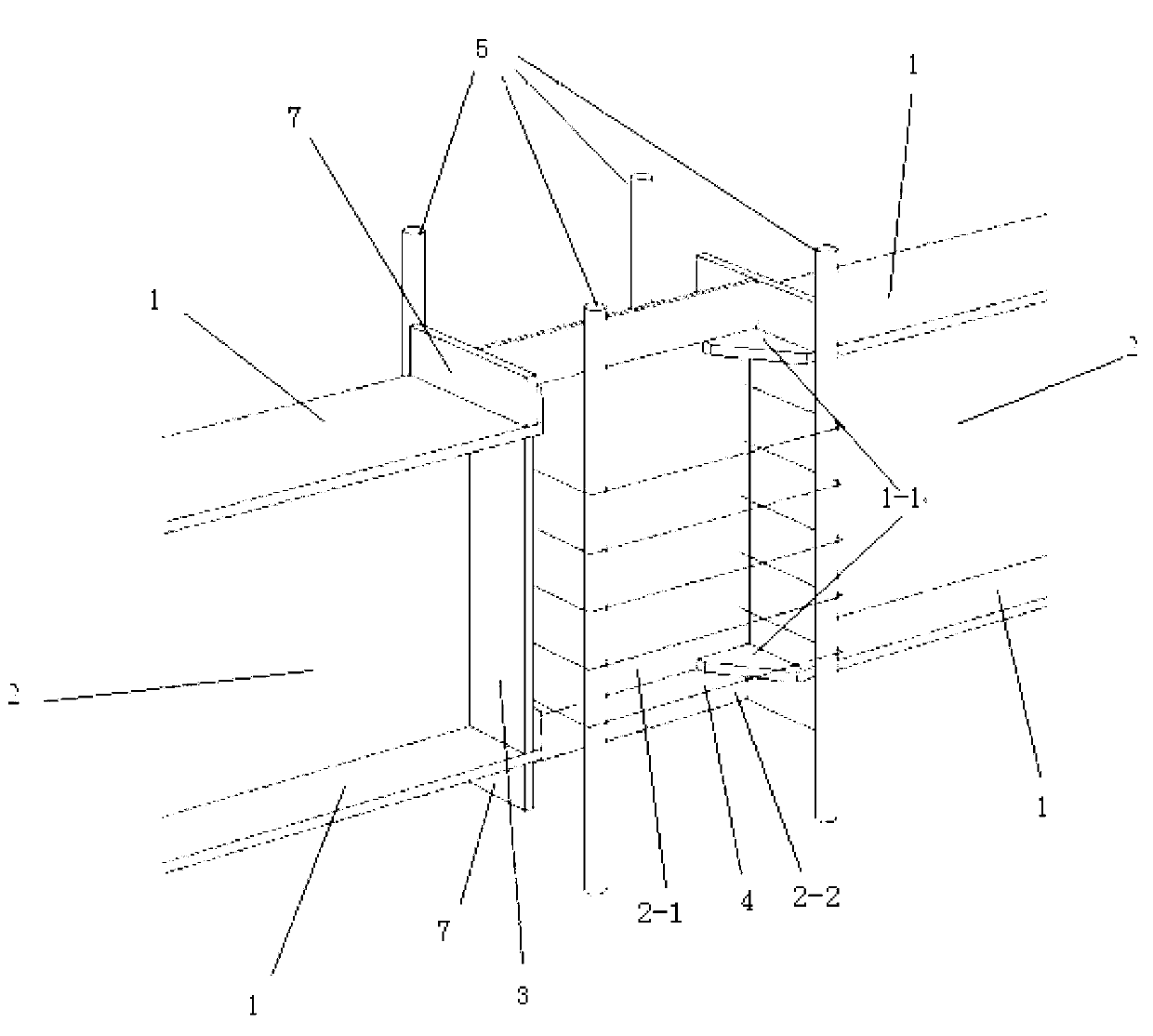
[0029] Such as figure 1 As shown, the RCS composite joint with continuous web and partially cut flange includes a reinforced concrete column and a steel beam vertically passing through the reinforced concrete column. or use section steel), the reinforced concrete column is composed of longitudinal steel bar 5, several layers of horizontally distributed stirrups 4 that are close to and around the longitudinal steel bar 5, and the steel beam flange that vertically passes through the reinforced concrete column is cut off, and the surrounding frame of the stirrup bar 4 passes through Through the joint web 2-1 connected with the steel beam web 2; the two ends of the joint web 2-1 are vertically distributed with surface bearing plates 3, and the surface bearing plates 3 are placed between the upper and lower flanges 1 of the steel beam; The core node is co...


PUM


Abstract

The invention discloses an RCS (reinforced concrete structure) combined node with continuous webs and partially-cut flanges, comprising a reinforced concrete column, and a steel beam which vertically penetrates through the reinforced concrete column, wherein the steel beam is formed by vertically connecting a steel beam web with steel beam flanges on the two end parts; the reinforced concrete column is composed of a longitudinal reinforcement, a plurality of layers of horizontally-distributed stirrups clinging to and surrounding the longitudinal reinforcement, and inter-column pouring concrete, the steel beam flanges which vertically penetrate through the reinforced concrete column are partially cut off, the stirrups penetrate through a node web which is connected with the steel beam web, and surface bearing plates are vertically distributed at the both ends of the node web; and a core node is composed of the longitudinal reinforcement in the reinforced concrete column, the stirrups surrounding the longitudinal reinforcement, the two surface bearing plates, the node web and steel beam flange extending ends of the partially-cut steel beam flanges. The steel web at the core node is mainly used for bearing a shearing force, the steel beam flange extending ends and the surface bearing plates are used for restraining concrete at the core node, so that the anti-shearing bearing force of the node is greatly improved.

Description

technical field [0001] The invention relates to a steel and concrete composite structure, in particular to a reinforced concrete column-steel beam composite node, that is, an RCS composite node with continuous webs and partially cut flanges. Background technique [0002] Reinforced concrete column-steel beam composite frame structure (composite frame consisting of Reinforced Concrete column and Steel beam, referred to as RCS) gives full play to the advantages of different materials of reinforced concrete and steel members, and is a low-cost and high-efficiency structural form. The reinforced concrete column-steel beam structure system is a kind of inheritance and development of pure steel structure and reinforced concrete structure, which has more excellent mechanical performance and economy. Generally speaking, compared with pure steel structures, reinforced concrete columns have better compressive performance, greater rigidity, durability and fire resistance, thereby savin...

Claims


Application Information

Patent Timeline
Patent Type & Authority Applications(China)
IPC IPC(8): E04B1/58E04B1/41
Inventor 门进杰郭智峰周琦王秋维史庆轩张兴虎
Owner XI'AN UNIVERSITY OF ARCHITECTURE AND TECHNOLOGY
Why Eureka
Try Eureka