
Efficient radial flow adsorption tower

An adsorption tower and radial flow technology, applied in the field of providing high-efficiency radial flow adsorption towers, can solve the problems of large equipment volume, high cost, and strict requirements for airflow distribution calculation.

Inactive Publication Date: 2013-03-27
田原宇
View PDF4 Cites 4 Cited by
  • Summary
  • Abstract
  • Description
  • Claims
  • Application Information

AI Technical Summary

Problems solved by technology

[0004] The domestic adsorber structure generally adopts the axial flow adsorption bed structure, which is the mainstream at present. Its advantages are simple structure and low manufacturing cost. The impact is relatively large, the dead space of the container is relatively large, and the volume of the equipment is also large, so the requirements for the calculation of airflow distribution are relatively strict; in addition, in order to improve the processing capacity, the diameter of the axial flow adsorption tower is super large, which causes inconvenience in manufacturing and transportation, and frequent positive pressure inlet The vibration of the large-diameter orifice plate caused by air and negative pressure suction will cause the wire mesh to loosen and rupture, resulting in the pulverization and fluidization of the molecular sieve
[0005] Compared with the axial adsorption tower, the radial flow adsorption tower has a large single-bed processing capacity, a small bed pressure drop, can force the gas to be evenly distributed, and has a small footprint. Molecular sieve pulverization, fluidization, convenient tower layout and other advantages, but there are also defects such as relatively complex structure, difficulty in designing uniform airflow distribution, and high cost
At present, radial flow adsorption towers both at home and abroad are fed at the bottom, and the radial feed is realized after the gas is changed. The radial gas distribution needs to be realized by changing the cross-sectional area, and the design is difficult.

Method used


Image

  • Efficient radial flow adsorption tower

Examples


Embodiment

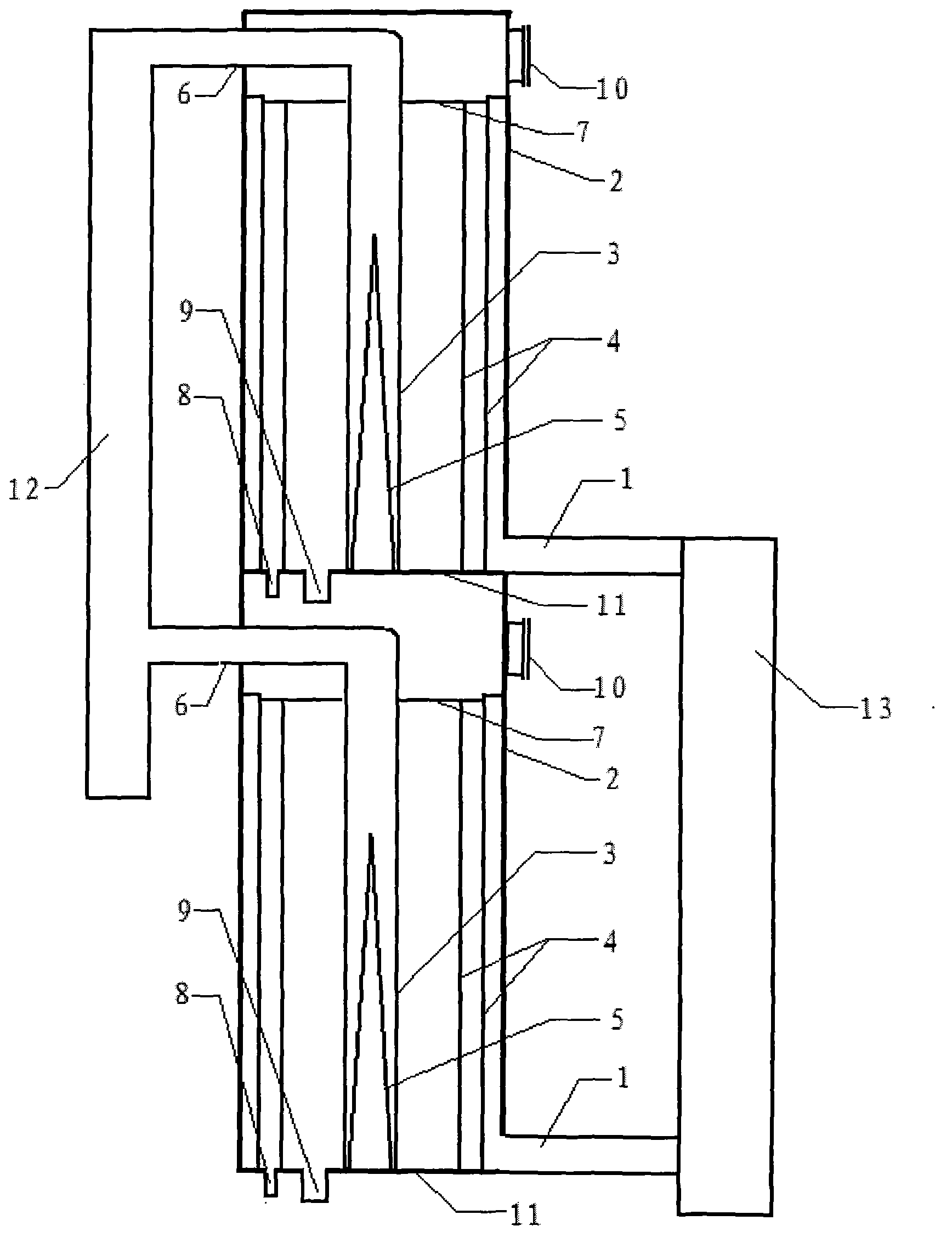
[0019] Embodiment, high-efficiency radial flow adsorption tower, consists of tangential air inlet (1), tower wall (2), central pipe (3), isolation cylinder (4), anti-dead zone guide cone cylinder (5), adsorption tail gas Outlet (6), adsorbent compression plate (7), auxiliary adsorbent discharge port (8), adsorbent discharge port (9), manhole (10), bottom plate (11), main pipe for adsorption tail gas (12 ), the main air intake duct (13) is formed. Each section of the adsorption tower is arranged in concentric circles from the outside to the inside by the tower wall (2), the isolation cylinder (4) and the center pipe (3). The top of the isolation cylinder (4) and the center pipe (3) passes through the adsorbent compression plate (7) Form the upper part of the adsorption section and seal; The central tube (3) forms an adsorption chamber, and the inner bottom of the central tube (3) is provided with an anti-dead zone guide cone (5); the bottom side of the tower wall (2) is connec...


PUM

PropertyMeasurementUnit
Diameteraaaaaaaaaa
Apertureaaaaaaaaaa

Abstract

The invention provides an efficient radial flow adsorption tower. Each section of the adsorption tower is formed by sequentially arranging a tower wall, separation cylinders and a central pipe from outside to inside according to a concentric circle, wherein an air chamber is formed by the tower wall and one separation cylinder; an auxiliary adsorption chamber is formed between the separation cylinder and the separation cylinder; an adsorption chamber is formed between one separation cylinder and the central pipe; a tangential air inlet is connected with the side face of the bottom of the tower wall; an adsorption tail gas outlet is connected with the central pipe and is arranged on the side face of the upper part of the tower wall; a manhole is distributed at the opposite side of the adsorption tail gas outlet; the tower wall, the central pipe and the separation cylinders are in sealed connection with a bottom plate; an auxiliary adsorbent unloading opening and an adsorbent unloading opening are respectively mounted at the bottoms of the auxiliary adsorption chamber and the adsorption chamber; the efficient radial flow adsorption tower is formed by 10-20 tower sections; each section is completely separated from the next section through the bottom plate; the adsorption tail gas outlet of each section is commonly connected to an adsorption tail gas main pipeline; and the tangential air inlet of each section is connected from a main air inlet pipeline.

Description

1. Technical field [0001] The invention provides a high-efficiency radial flow adsorption tower, which belongs to the field of chemical separation. 2. Background technology [0002] A gas purification device that uses a porous active solid adsorbent to treat a gas mixture so that one or several components are concentrated on the surface of the adsorbent to separate it from the gas flow is one of the main types of gas purification equipment. First, it belongs to dry purification equipment. Adsorption equipment is widely used in chemical industry, medicine, food, light industry, environmental protection and other industries, such as deep drying of gas and liquid; decolorization and deodorization of food, medicine, organic petroleum products; organic isomers (such as mixed xylene) Separation; air separation to produce oxygen-enriched air; removal of harmful substances from waste water or waste gas, etc. The general adsorption operation includes three steps: contact adsorption...

Claims


Application Information

Patent Timeline
IPC IPC(8): B01D53/04
Inventor 田原宇乔英云
Owner 田原宇
Learn More