Vacuum cleaner including muffler and air diffuser

A vacuum cleaner and muffler technology, which is applied in the direction of vacuum cleaners, exhaust diffusers, cleaning equipment, etc., can solve the problems of not allowing to reduce noise emissions, large size and volume, etc.

Inactive Publication Date: 2016-10-26
SEB SA
View PDF11 Cites 0 Cited by
  • Summary
  • Abstract
  • Description
  • Claims
  • Application Information

AI Technical Summary

Problems solved by technology

Such an air outlet does not allow to reduce noise emissions, and the divergence with the function of generating laminar flow is arranged between the restriction neck and the outlet filter and requires a large length and a large space to be given to the discharge system inside the device, so that the Exhaust system is large in size and volume

Method used


Image

  • Vacuum cleaner including muffler and air diffuser
  • Vacuum cleaner including muffler and air diffuser
  • Vacuum cleaner including muffler and air diffuser

Examples


Embodiment Construction

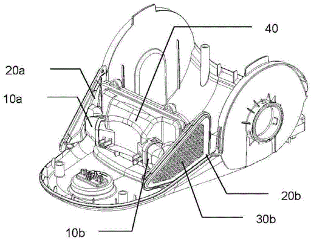
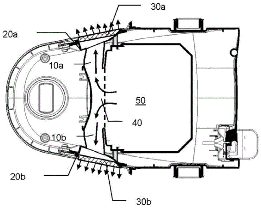
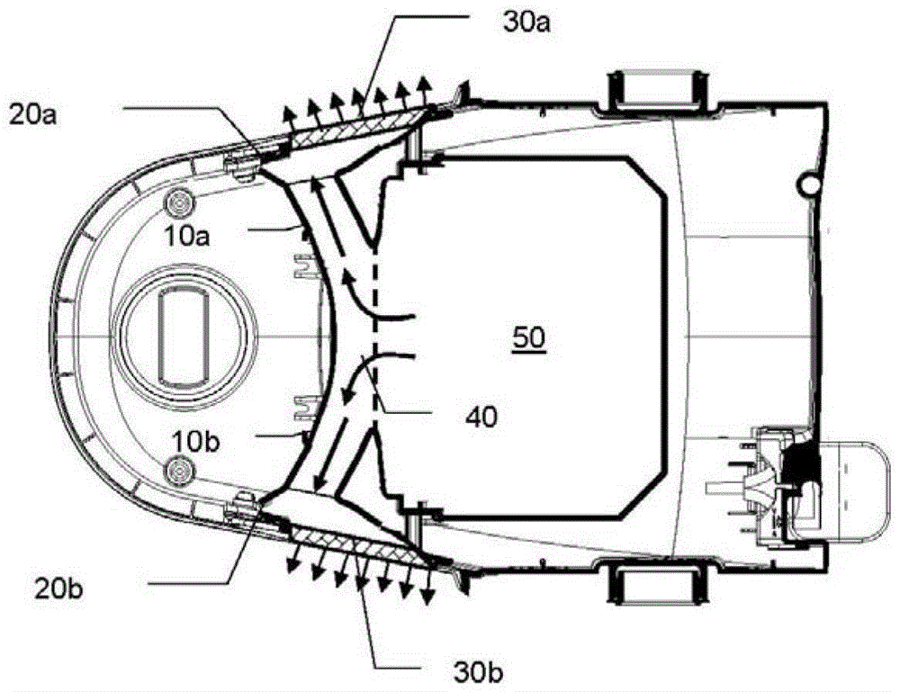
[0021] figure 1 Part of a vacuum cleaner is shown. The air collector 40 collects air exhausted by an unillustrated motor arranged at the rear of the cleaner. The collector 40 then distributes the air towards two exhaust circuits, each comprising a muffler formed by the elongated confinement portions 10a and 10b. The effect of these elongated limits of constant cross-section is to reduce the influence of the noise emitted by the air flow expelled by the motor. The two restricting parts 10a and 10b are then each connected to a porous diffuser 30a and 30b via two diffuse fitting parts 20a and 20b respectively, which are structural parts of the housing of the vacuum cleaner.

[0022] figure 2 show figure 1 Horizontal cutaway view of a vacuum cleaner. Thus, the motor 50 expels the air towards the collector 40, which then divides the air flow and directs it towards the two restricted portions 10a and 10b. Restriction portions 10a and 10b are connected to porous diffusers 30a ...


PUM


Abstract

The vacuum cleaner has a motor fan, which sucks air flow and supplies this air to a discharge circuit, which has a channel with longitudinally extended neckings (10a,10b) with constant air flow-passage cross section, which has an exhaust silencer. The discharge circuit has transition pieces (20a,20b), which is arranged between the longitudinally extended necking and the porous diffusor (30b). The transition piece has a diverging air flow-passing cross section.

Description

technical field [0001] The present invention relates generally to vacuum cleaners, and more particularly to the air discharge of vacuum cleaners. Background technique [0002] Exhaust openings for the purpose of reducing the exhaust noise of equipment are known in the prior art, which comprise a restriction of significantly reduced size in order to obtain a sound dampening effect. [0003] Document US4651380 discloses a vacuum cleaner with a muffler of constant section followed by a diffuser. The outlet jets of such vacuum cleaners are concentrated, and their velocity and direction characteristics can either cause discomfort to the user, because the jets are concentrated at high speeds in a small area, or cause eddies on the ground, which can The dust on the ground that the user wants to inhale is dispersed in the air. [0004] The document GB2117229 itself proposes a vacuum cleaner comprising two air outlets, which are formed for the purpose of reducing noise. An elongat...

Claims


Application Information

Patent Timeline
Patent Type & Authority Patents(China)
IPC IPC(8): A47L9/00
CPCA47L9/0081
Inventor 费比安·大卫
Owner SEB SA
Why Eureka
Try Eureka