Three-dimensional image display apparatus
A technology of display device and stereoscopic video, which can be applied to stereoscopic systems, optics, instruments, etc., and can solve the problems such as hindering the thinning of display devices, and the inability to arrange cylindrical lenses and display parts in close proximity.
- Summary
- Abstract
- Description
- Claims
- Application Information
AI Technical Summary
Problems solved by technology
Method used
Image

Examples
Embodiment approach 1
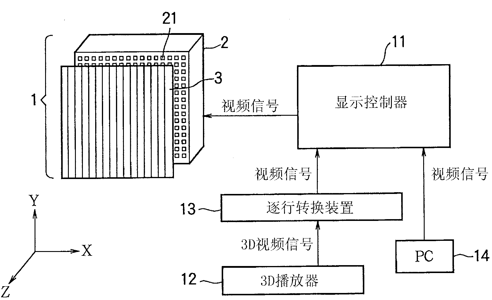
[0025] figure 1 It is a diagram showing the basic configuration of a stereoscopic video display system including the large stereoscopic video display device 1 (stereoscopic video display device) in Embodiment 1 of the present invention. The large stereoscopic video display device 1 uses LEDs (Light Emitting Diodes) as display pixels, and is a display device that displays video on a large screen of, for example, 32 inches or more. The large stereoscopic video display device 1 has an LED display unit 2 as a display unit and a front lens 3 arranged in front of the LED display unit 2 .
[0026] The LED display unit 2 is connected to a display controller (display control unit) 11 that has a video signal adjustment function and outputs a video signal. A progressive conversion device 13 is connected to the display controller 11 , and a 3D player (player device) 12 capable of outputting a 3D video signal (stereoscopic video signal) is connected to the progressive conversion device 13...
Embodiment approach 2
[0078] Next, a large stereoscopic video display device according to Embodiment 2 of the present invention will be described. The overall configurations of the large-scale stereoscopic video display device and the stereoscopic video display system in Embodiment 2 are the same as those described in Embodiment 1.
[0079] Figure 7 It is a plan view showing an optical system including the LED display unit 5 and the front lens 3 of the large-scale stereoscopic video display device in the second embodiment. The LED display unit 5 has LEDs 51 as display pixels. The LEDs 51 are arranged in a matrix at a certain arrangement interval d in both the X direction and the Y direction. LED51 has the same structure as LED 21 demonstrated in Embodiment 1, but is smaller than LED 21 in size.
[0080] In this Embodiment 2, LED51 is divided by the partition wall 52, respectively. The partition walls 52 are formed, for example, in a lattice shape in the X direction and the Y direction. The pa...
Embodiment approach 3
[0117] Next, a large-scale stereoscopic video display device according to Embodiment 3 of the present invention will be described. The overall configurations of the large-scale stereoscopic video display device and the stereoscopic video display system in Embodiment 3 are the same as those described in Embodiment 1.
[0118] Figure 10 (A) and Figure 10 (B) is a plan view and a side view showing an optical system including the LED display unit 6 and the front lens 3 in the third embodiment. The structure of the LED display part 6 of Embodiment 3 is basically the same as that of the LED display part 5 of Embodiment 2 ( Figure 7 ~ Figure 9 ) are the same, except that a sun visor (sun visor) 61 is provided on the exit side (front lens 3 side) and above the diffusion sheet 53 corresponding to each LED 51, and the sun visor 61 is used as a light shielding member to avoid light from above. Light (for example, external light such as sunlight) directly enters the diffusion sheet ...
PUM
 Abstract
Description
Claims
Application Information
 - R&D
- Intellectual Property
- Life Sciences
- Materials
- Tech Scout
- Unparalleled Data Quality
- Higher Quality Content
- 60% Fewer Hallucinations
Browse by: Latest US Patents, China's latest patents, Technical Efficacy Thesaurus, Application Domain, Technology Topic, Popular Technical Reports.
© 2025 PatSnap. All rights reserved.Legal|Privacy policy|Modern Slavery Act Transparency Statement|Sitemap|About US| Contact US: help@patsnap.com