
A protective device for polysilicon ingot crucible

A protection device, polysilicon technology, applied in the direction of polycrystalline material growth, crystal growth, silicon compounds, etc., can solve the problems of polycrystalline silicon quality influence, no cover plate, impurities entering silicon melt, etc., to improve the utilization rate and slicing efficiency. rate, reduce precipitation and agglomeration, improve the effect of gas circulation

Active Publication Date: 2015-09-30
东海晶澳太阳能科技有限公司 +1
View PDF2 Cites 0 Cited by
  • Summary
  • Abstract
  • Description
  • Claims
  • Application Information

AI Technical Summary

Problems solved by technology

However, when using directional solidification method for polysilicon casting, the following two problems are usually encountered: First, due to the quality problems of the crucible itself, or abnormalities such as knocking on the crucible during the charging process, the crucible may break and occur. The accident of liquid silicon overflow brought losses to production; secondly, when casting polysilicon ingots, most manufacturers used crucible guard plates instead of cover plates, or used ordinary C / C plates as cover plates, This method will cause impurities in the C / C insulation material and C / C plate in the ingot furnace to enter the silicon melt, affecting the quality of polysilicon
As stated in the second question, during the polysilicon ingot casting process, impurities in insulating materials, graphite shields and C / C plates, especially C, will enter the polysilicon in large quantities, which will greatly affect the quality of the polysilicon
In order to solve this problem, the method of improving the material of the insulation material is generally adopted, and the C / C material with high purity and solid material is used. This method has a certain effect on the control of impurities in polysilicon, but it inevitably increases the production cost.

Method used


Image

  • A protective device for polysilicon ingot crucible
  • A protective device for polysilicon ingot crucible
  • A protective device for polysilicon ingot crucible

Examples


Embodiment 1

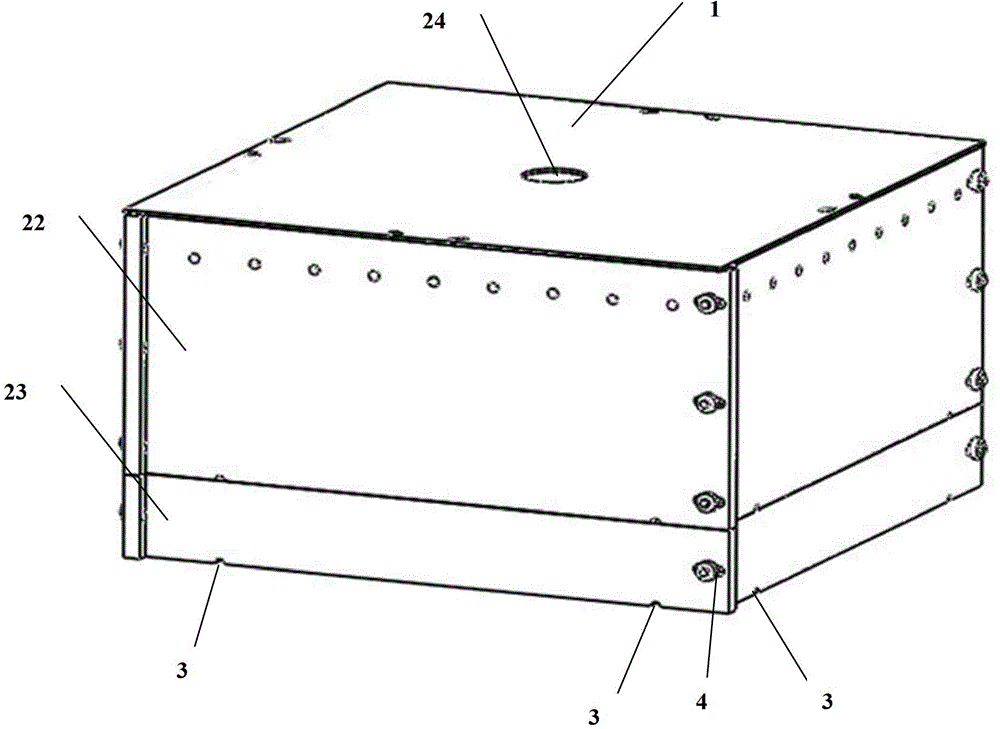
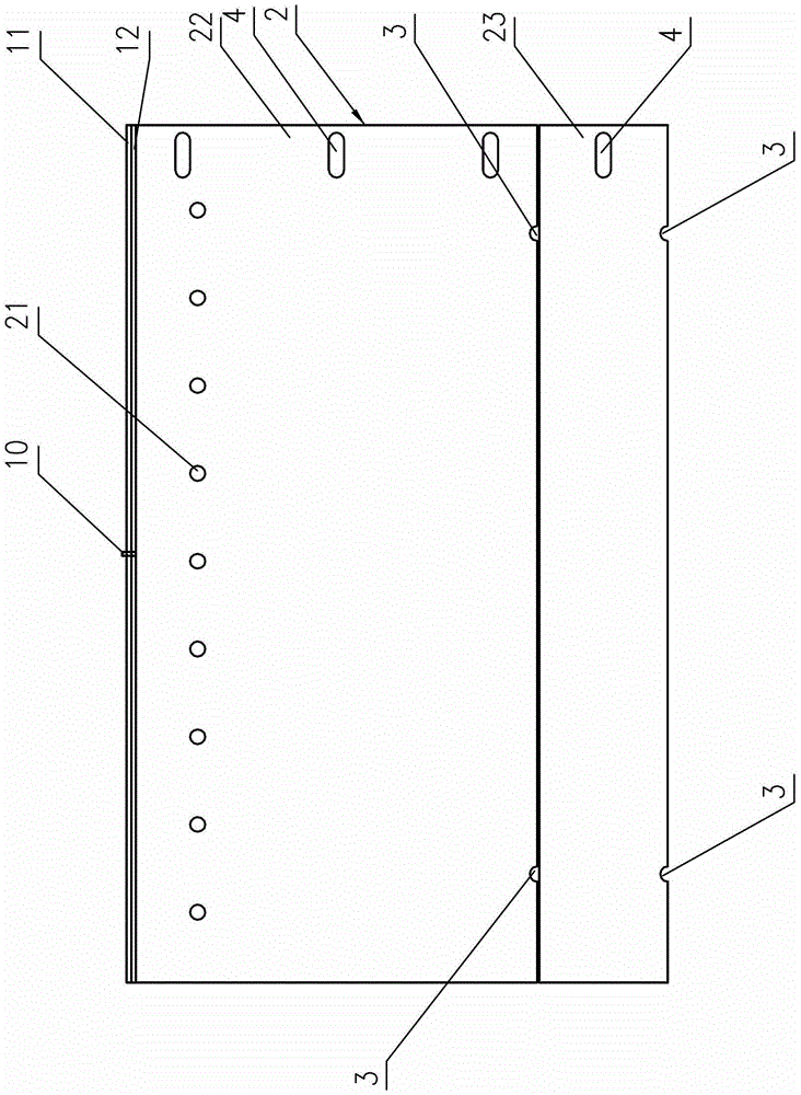
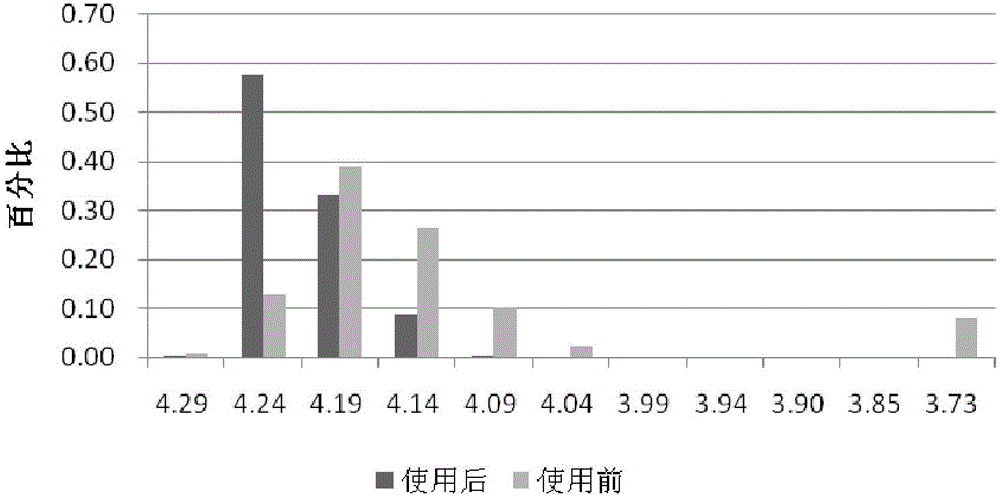
[0033] Such as Figure 1~3As shown, it is a protective device for a polysilicon ingot crucible according to the present invention, which includes a guard plate formed by connecting vertical plates in twos, and a cover plate 1 and a bottom plate respectively arranged on the guard plate and the lower end (not shown in the figure) , the cover plate 1 is fastened to the opening of the upper end of the guard plate 2 to form an inner space for placing the polysilicon ingot crucible, and the cover plate 1 is composed of a common C / C plate 11 and a metal plate combined on the lower surface of the C / C plate 11 12 components, wherein the melting point of the metal plate 12 is greater than 1800K; the upper part of the guard plate 2 has an air outlet 21 and the air outlet 21 corresponds to the top of the polysilicon ingot crucible, and the cover plate is opened through the C / C plate 11 and the metal plate 12 The air inlet 24 for feeding argon into the inner space is used to ventilate the ...

Embodiment 2

[0041] The guard plate assembly of this embodiment has three layers (not shown in the figure), that is, the guard plate is composed of a lower layer, a middle layer, and an upper layer guard plate assembly. There are four board bodies in the upper and lower layer guard plate assemblies. There are two plate bodies in the guard plate assembly; two overflow holes are arranged on the lower edge of each plate body of the lower guard plate assembly. The upper guard plate assembly is provided with an air outlet, and the air outlet is a circular hole. In this embodiment, the center of the air outlet is 40 mm from the upper edge of the upper guard plate assembly. The distance between adjacent air outlets is 62mm, and the diameter of the air outlets is 16mm.

[0042] In the three-layer guard plate assembly, the board heights of the adjacent two-layer guard board assemblies are different, and the higher part of the higher board body relative to the other board bodies in this guard board ...

Embodiment 3

[0046] The shield assembly of the present embodiment has four layers, and the shield is composed of the superposition of the lower layer, the middle layer, the upper middle layer and the upper layer board assembly, and the number of board bodies in each layer of shield assembly is four; Three overflow holes are arranged on the lower edge of each plate body. The upper guard plate assembly is provided with an air outlet, and the air outlet is a circular hole. In this embodiment, the center of the air outlet is 80 mm from the upper edge of the upper guard plate assembly, and each plate body of the upper guard plate assembly is equidistantly provided with 14 Air outlets, the distance between adjacent air outlets is 54mm, and the diameter of the air outlets is 20mm.

[0047] The height of each plate body in the lower guard plate assembly is 80mm, and one side of each plate body is provided with a screw hole, and the end face of one side of the adjacent plate body is also provided w...


PUM

PropertyMeasurementUnit
diameteraaaaaaaaaa
diameteraaaaaaaaaa
heightaaaaaaaaaa

Abstract

The invention discloses a protective device for a polysilicon ingot casting crucible. The protective device comprises a guard board formed by enclosure of vertical plates mutually connected and a cover plate and base plate respectively arranged at the upper end and the lower end of the guard board, wherein the cover plate is covered on an opening of the upper end of the guard board through buckling to form internal space used for disposing the polysilicon ingot casting crucible and is mainly composed of a C / C plate and a metal plate bonded with the lower surface of the C / C plate, the melting point of the metal plate is greater than 1800 K, the upper part of the guard board is provided with an air outlet which is correspondingly arranged above the polysilicon ingot casting crucible, the cover plate is provided with an air inlet penetrating the C / C plate and the metal plate, and air-exchanging and ventilation for the internal space is realized through the air inlet and the air outlet so as to improve gas cycle in the process of ingot casting to purify a fusing and re-growth environment of polysilicon. According to the invention, the content of impurities like C and O in polysilicon is greatly reduced, the utilization rate of a silicon material and a slice yield rate are improved, and transfer efficiency of a silicon chip can be improved by more than 0.2%.

Description

technical field [0001] The invention relates to the technical field of photovoltaic utilization of crystalline silicon solar energy, in particular to a protective device for a polycrystalline silicon ingot crucible. Background technique [0002] Among the various preparation methods of polysilicon used in the solar photovoltaic industry, the silicon ingot produced by the directional solidification method has a large weight in a single furnace and low average energy consumption, so it is widely used. However, when using directional solidification method for polysilicon casting, the following two problems are usually encountered: First, due to the quality problems of the crucible itself, or abnormalities such as knocking on the crucible during the charging process, the crucible may break and occur. The accident of liquid silicon overflow brought losses to production; secondly, when casting polysilicon ingots, most manufacturers used crucible guard plates instead of cover plate...

Claims


Application Information

Patent Timeline
Patent Type & Authority Patents(China)
IPC IPC(8): C30B28/06C30B29/06C01B33/037
Inventor 黄新明明亮钟根香
Owner 东海晶澳太阳能科技有限公司
Learn More