rotary compressor

A rotary compressor and cylinder technology, applied in rotary piston machinery, rotary piston pumps, rotary piston/oscillating piston pump components, etc., can solve problems such as increased sliding loss

Active Publication Date: 2015-09-09
PANASONIC INTELLECTUAL PROPERTY MANAGEMENT CO LTD
View PDF7 Cites 1 Cited by
  • Summary
  • Abstract
  • Description
  • Claims
  • Application Information

AI Technical Summary

Problems solved by technology

Therefore, frictional resistance with the vane groove 10 acts at the contact points 201 and 202 of the vane 11 and the vane groove 10 as a reaction force of the support force, and the sliding loss due to the reciprocating movement of the vane 11 in the vane groove 10 increases.

Method used


Image

  • rotary compressor
  • rotary compressor
  • rotary compressor

Examples


Embodiment approach 1

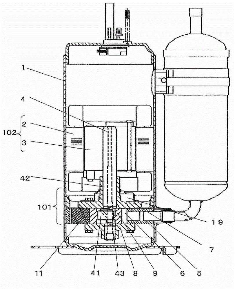
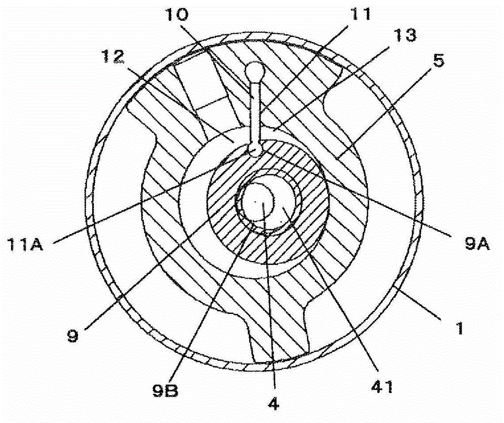
[0041] figure 1 It is a longitudinal sectional view of a rotary compressor provided with one compression mechanism unit 101 as an embodiment of the rotary compressor of the present invention, figure 2 is a cross-sectional view showing the compression mechanism.

[0042] like figure 1 The illustrated rotary compressor includes: a cylindrical airtight container 1; an electric motor unit 102 arranged on the upper side of the airtight container 1; Part 101 uses the bottom of the airtight container 1 as an oil tank.

[0043] The motor part 102 includes: the stator 2 installed annularly along the inner peripheral surface of the inner upper side of the airtight container 1; The direction is fixed to axis 4.

[0044] like figure 1 and figure 2 As shown, the compression mechanism part 101 has: a cylinder 5; a main bearing 7 and a sub-bearing 8 that connect the two end faces of the cylinder 5 to form a cylinder chamber 6; 4; the piston 9 fitted in the eccentric portion 41 of...


PUM


Abstract

In a rotary compressor of a vane rotary type, an outer peripheral surface of an eccentric portion 41 of a shaft 4 on a side adjacent to a center of the shaft 4 is located radially inwardly of an outer peripheral surface of a main shaft 42 inserted in a main bearing 7 and that of an auxiliary shaft 43 inserted in an auxiliary bearing 8. Also, a back clearance means used in mounting a piston 9 on the shaft 4 is provided in each of an inner peripheral surface of the piston 9 and the eccentric portion 41 of the shaft 4. Such configurations can reduce a diameter of the eccentric portion 41. A reduction in diameter of the eccentric portion 41 can reduce a viscous force of oil acting between the eccentric portion 41 of the shaft 4 and the inner peripheral surface of the piston 9 to thereby reduce a rotational moment about a center of the eccentric portion 41 of the shaft 4, which rotational moment acts on the piston 9 in a direction of rotation of the shaft 4, thus making it possible to reduce a sliding loss that is generated by a reciprocating motion of a vane 11 in a vane groove 10.

Description

technical field [0001] The present invention relates to a rotary compressor incorporated in refrigerators, air conditioners, and the like. Background technique [0002] State-of-the-art rotary compressors such as Figure 7 with Figure 8 As shown, a motor unit (not shown) and a compression mechanism unit A connected to the motor unit via a shaft 4 are housed in the airtight container 1 , and the bottom of the airtight container is used as an oil tank. The compression mechanism part A includes: a cylinder 5; a main bearing 7 and a sub-bearing 8 that are connected to both end faces of the cylinder 5 to form a cylinder chamber 6; a shaft 4 with an eccentric portion 41 between the main bearing 7 and the sub-bearing 8; Piston 9 fitted to eccentric portion 41 of shaft 4 ; and vane 11 reciprocating in vane groove 10 formed in the radial direction of cylinder 5 . In this way, the suction chamber 12 and the compression chamber 13 separated by the vane 11 are formed in the cylinder ...

Claims


Application Information

Patent Timeline
Patent Type & Authority Patents(China)
IPC IPC(8): F04C18/324F04C29/00
CPCF04C29/0057F04C2240/60F04C18/04F04C18/324
Inventor 苅野健船越大辅饭田登泽井清
Owner PANASONIC INTELLECTUAL PROPERTY MANAGEMENT CO LTD
Why Eureka
Try Eureka