
High-frequency inductive welding joint

A high-frequency induction welding and welding head technology, which is applied in high-frequency current welding equipment, welding equipment, metal processing equipment, etc., can solve the problems of difficult to ensure the effect of welding workpieces and welding uniformity, and achieve ideal welding effects , to ensure the effect of uniformity

Active Publication Date: 2013-03-13
青岛同日智能技术有限公司 +1
View PDF5 Cites 14 Cited by
  • Summary
  • Abstract
  • Description
  • Claims
  • Application Information

AI Technical Summary

Problems solved by technology

[0002] High-frequency induction welding is a method of metal welding, which has the advantages of fast welding speed, high welding quality, and low environmental impact. The induction coils used in existing high-frequency induction welding guns are all circular structures or on a circular basis. It is difficult to ensure the uniformity of welding on some irregularly changing structures, especially in the welding of closed-loop pipelines. It is difficult to ensure the effect of welding workpieces with existing welding heads. Therefore, it is necessary to ensure the welding effect of high-frequency induction welding tools. Just must a kind of high-frequency induction welding head that can guarantee welding uniformity, but all do not see report in the prior art

Method used


Image

  • High-frequency inductive welding joint
  • High-frequency inductive welding joint

Examples


Embodiment Construction

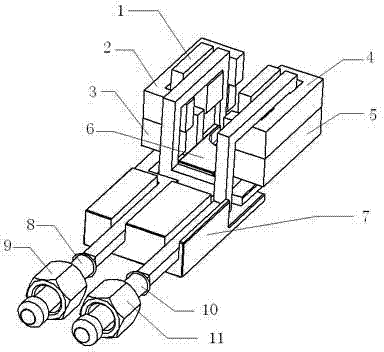
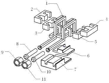
[0012] Such as figure 1 , 2 A high-frequency induction welding head is shown, including a square copper tube induction coil 1, an upper left ferrite core 2, a lower left ferrite core 3, an upper right ferrite core 4, and a lower right ferrite core 5. Positioning block 6, welding head bracket 7, left connecting pipe 8, right connecting pipe 9, said upper left ferrite core 2, lower left ferrite core 3, upper right ferrite core 4, lower right iron The ferrite core 5 is installed on the induction coil 1 of the square copper tube, in which the upper left ferrite core 2 and the lower left ferrite core 3, the upper right ferrite core 4 and the lower right ferrite core 5 are in two groups The magnetic cores all adopt an asymmetric structure; the positioning block 6 is installed under the square copper induction coil 1 and installed on the welding head bracket 7; the left connecting pipe 8 and the right connecting pipe 9 are connected to the square copper induction coil 1 and fixed o...


PUM


Abstract

The invention discloses a high-frequency inductive welding joint, which comprises a square copper tube induction coil, a left upper ferrite magnetic core, a left lower ferrite magnetic core, a right upper ferrite magnetic core, a right lower ferrite magnetic core, a positioning block, a welding head bracket, a left connecting tube and a right connecting tube, wherein the left upper ferrite magnetic core, the left lower ferrite magnetic core, the right upper ferrite magnetic core and the right lower ferrite magnetic core are arranged on the square copper tube induction coil; unequal structures are adopted for the left upper ferrite magnetic core and the left lower ferrite magnetic core as well as the right upper ferrite magnetic core and the right lower ferrite magnetic core; the positioning block is arranged below the square copper tube induction coil, and is arranged on the welding head bracket; and the left connecting tube and the right connecting tube are connected to the square copper tube induction coil, and are fixedly arranged on the welding head bracket. Due to the adoption of the high-frequency inductive welding joint, the welding uniformity can be ensured effectively, and a very ideal welding effect is achieved.

Description

technical field [0001] The invention relates to a welding tool part, in particular to a high-frequency induction welding head. Background technique [0002] High-frequency induction welding is a method of metal welding, which has the advantages of fast welding speed, high welding quality, and low environmental impact. The induction coils used in existing high-frequency induction welding guns are all circular structures or on a circular basis. It is difficult to ensure the uniformity of welding on some irregularly changing structures, especially in the welding of closed-loop pipelines. It is difficult to ensure the effect of welding workpieces with existing welding heads. Therefore, it is necessary to ensure the welding effect of high-frequency induction welding tools. Just must a kind of high-frequency induction welding head that can guarantee welding uniformity, but all do not see report in the prior art. Contents of the invention [0003] The purpose of the present inve...

Claims


Application Information

Patent Timeline
Patent Type & Authority Applications(China)
IPC IPC(8): B23K13/01
Inventor 迟存健蒋辉唐辉彭岩闫法民
Owner 青岛同日智能技术有限公司
Learn More