Driving method of liquid crystal panel and driving circuit thereof
A technology of liquid crystal panel and driving method, which is applied in the direction of instruments, static indicators, etc., can solve the problem of insufficient uniformity (display effect consistency) effect, etc., to achieve better screen display effect, high flexibility, and uniformity Good results
- Summary
- Abstract
- Description
- Claims
- Application Information
AI Technical Summary
Problems solved by technology
Method used
Image

Examples
Embodiment 1
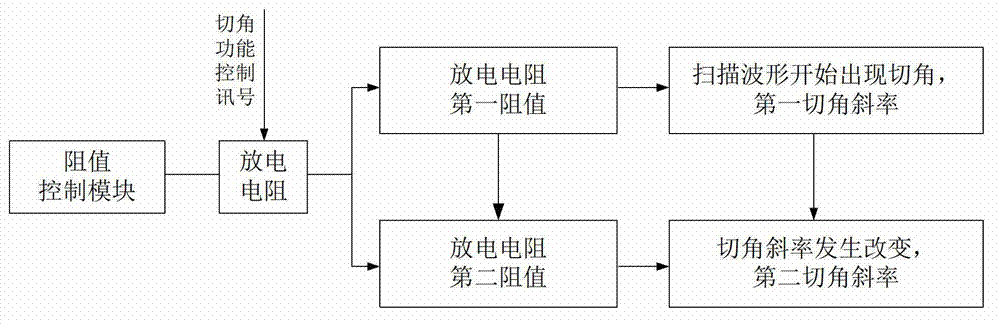
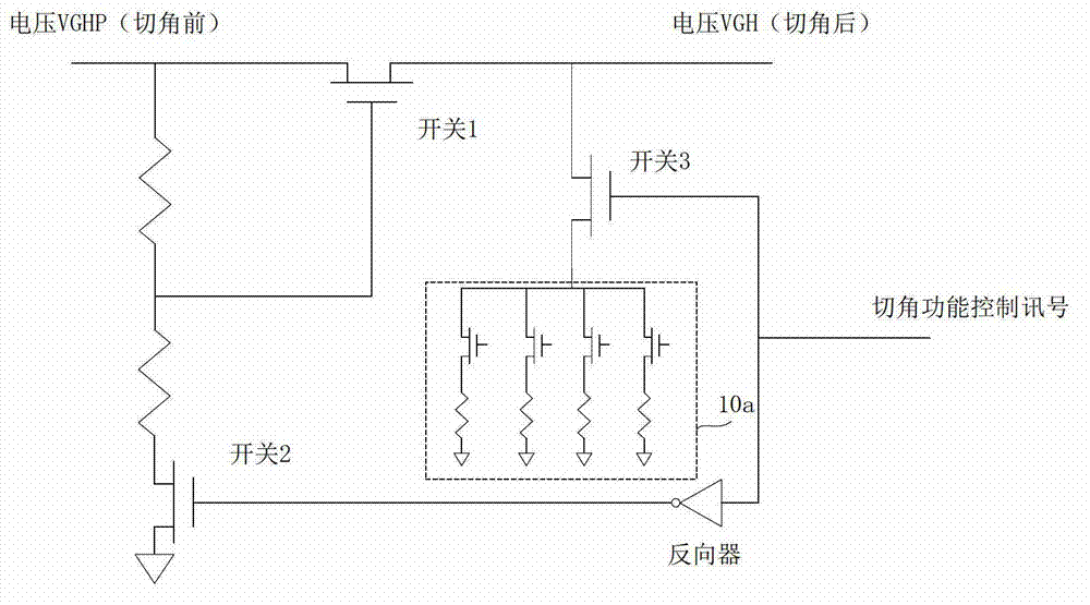
[0034] like image 3 and Figure 4 As shown, the discharge resistor 10 in the corner-cutting circuit is a digital resistor 10a with adjustable resistance, and a resistance control module is provided outside the corner-cutting circuit to directly adjust the resistance of the digital resistor to change the discharge resistance (that is, the digital resistor) at The resistance value during the continuous discharge process, the change of the resistance value of the discharge resistance will cause the slope of the cutting angle of the scanning waveform to change. The digital resistor includes a plurality of sub-resistors 11 connected in parallel, each sub-resistor 11 is connected in series with a resistance adjustment switch 31, and the discharge slope control module sends a digital control signal to control the switch 31 of the corresponding sub-resistor 11 in the digital resistor to obtain the required Resistance value, the digital resistor 10 is connected in series with the mai...
Embodiment 2
[0040] like Figure 8 As shown, the difference from the first embodiment is that the corner cutting circuit in this embodiment is provided with two discharge resistors, and the two discharge resistors are respectively provided with a switch 3 and a switch 4 . By controlling the conduction of the switch 3 and the switch 4, the slope of the cutting angle can be changed. The specific control can be expressed as: first turn on switch 3 and switch 4, at this time the slope of the cutting angle of the scanning waveform is the first slope of the cutting angle, then turn off switch 4, at this time only one discharge resistor is discharged, and the slope of the cutting angle of the scanning waveform is is the slope of the second chamfer.
Embodiment 3
[0042] The present invention also provides a uniformity adjustment system for liquid crystal panels, such as Figure 9 Shown is a specific embodiment of the system, the system includes: a corner cutting IC, the corner cutting IC is provided with an adjustable resistor with adjustable resistance; a corner cutting control fixture is used to deliver the corner cutting function to the corner cutting IC Control signal and resistance control signal; panel brightness measuring instrument, used to measure the difference in brightness of the sub-regions of the liquid crystal panel 200, and feed back the information of the difference in brightness of the sub-regions to the corner cutting control fixture; the corner cutting control fixture according to the The brightness difference information of the partitions sends the resistance control signal to the corner cutting IC, and the corner cutting IC charges the driving IC 210 of the liquid crystal panel according to the corner cutting funct...
PUM
 Abstract
Description
Claims
Application Information
 - R&D
- Intellectual Property
- Life Sciences
- Materials
- Tech Scout
- Unparalleled Data Quality
- Higher Quality Content
- 60% Fewer Hallucinations
Browse by: Latest US Patents, China's latest patents, Technical Efficacy Thesaurus, Application Domain, Technology Topic, Popular Technical Reports.
© 2025 PatSnap. All rights reserved.Legal|Privacy policy|Modern Slavery Act Transparency Statement|Sitemap|About US| Contact US: help@patsnap.com