
Network diagnosis method, system and equipment based on software defined network

A network diagnosis and controller technology, applied in the field of network communication, can solve problems such as violation of core concepts, difficulty in determining the location of network faults, and inability to report hardware information to the controller, so as to reduce operation and maintenance costs, speed up positioning cycle, and improve network quality effect

Active Publication Date: 2015-06-03
ZTE CORP
View PDF3 Cites 0 Cited by
  • Summary
  • Abstract
  • Description
  • Claims
  • Application Information

AI Technical Summary

Problems solved by technology

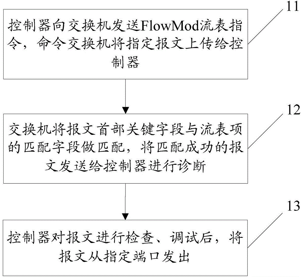
[0010] The current SDN-based network diagnosis method still has some deficiencies. First, the controller needs to send additional flow table instructions to the switch to notify the switch to send the specified packet to the controller. These additional flow table instructions may interfere with The existing flow table entries conflict, so that the switch cannot determine which flow table command to process according to which flow table instructions, so that the switch cannot correctly send the specified packet to the controller; secondly, the OpenFlow protocol cannot carry more detailed information on the forwarding plane of the switch, such as The register information of the switch chip, the memory data information, etc., resulting in these hardware information cannot be reported to the controller, making it difficult to determine the location of the network fault in a short time, increasing the difficulty of network diagnosis; third, the controller network diagnosis After the end, the message can only be sent out from the designated port, and the processing process of the message interruption cannot be continued, so that it is impossible to debug the network like software development and debugging, which violates the core concept of SDN

Method used


Image

  • Network diagnosis method, system and equipment based on software defined network
  • Network diagnosis method, system and equipment based on software defined network
  • Network diagnosis method, system and equipment based on software defined network

Examples


Embodiment Construction

[0066] The present invention will be further described in detail below in conjunction with the accompanying drawings and specific embodiments.

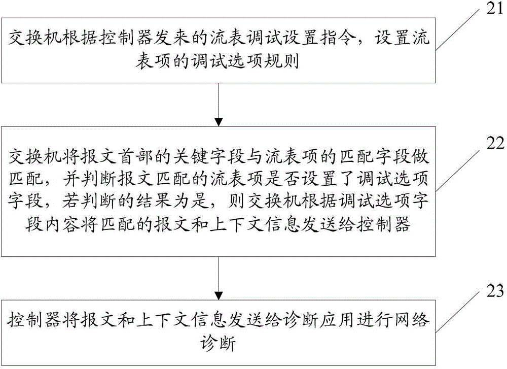
[0067] figure 2 It is a schematic flow chart of the SDN-based network diagnosis method of the present invention, such as figure 2 shown, including the following steps:

[0068] Step 21: The switch sets the debugging option rules of the flow entry according to the flow table debugging setting instruction sent by the controller;

[0069] Here, the controller can send a flow table debugging setting instruction to the switch through the debugging option capability interface of the controller itself to set the debugging option rule, and the flow table debugging setting instruction includes a flow table number, a matching field and a debugging option field; The debugging option field includes: sending to the controller, data flow log cache, etc.; the flow table debugging instruction can be carried by a standard protocol, such as the Ope...


PUM


Abstract

The invention discloses a network diagnosis method based on a software defined network (SDN). The method includes the steps that a switchboard sets the rule of debug option of a flow table item according to a flow table debug setting command sent by a controller; the switchboard matches the key field of the message heading with the matching field of the flow table item, and judges whether the flow table item matched with the message is set up with a debug option field or not; if yes, the switchboard executes relevant debugging operations according to the content of the debug option field, and the operations include, but not limited to, sending the matching message and the contextual information to the controller; and the controller proceeds network diagnosis according to the message and the contextual information. The invention further discloses a network diagnosis system and equipment based on the SDN. With the technical scheme provided by the invention, the cycle for positioning a network problem is accelerated, the quality of the network is improved, and the operating maintenance cost of the network is reduced.

Description

technical field [0001] The present invention relates to network communication technology, in particular to a network diagnosis method, system and equipment based on Software Defined Network (Software Defined Network, SDN). Background technique [0002] SDN is a new type of network innovation architecture. Its core is to build a network system that separates the forwarding plane and the control plane, and debug the network like software development and debugging to support the continuous evolution of network functions and realize flexible control of the network. [0003] SDN-based network problem diagnosis becomes easier than traditional network problem diagnosis. When a problem occurs in the traditional network, technical personnel of the relevant manufacturer need to collect logs on the device and diagnose it through the manufacturer's proprietary tools. Locating the fault is cumbersome and takes a long time. [0004] In the SDN architecture, taking the OpenFlow protocol a...

Claims


Application Information

Patent Timeline
Patent Type & Authority Patents(China)
IPC IPC(8): H04L12/24H04L12/26H04L12/937
Inventor 梁亮
Owner ZTE CORP
Learn More