Full-automatic oil separation lifting integrated device

A fully automatic, oil-separating technology, applied in chemical instruments and methods, water/sewage multi-stage treatment, water/sludge/sewage treatment, etc. Problems such as poor oil separation effect and poor sealing performance of oil separation pools can save civil construction investment costs, avoid waste in subsequent treatment, and facilitate rapid separation.

Inactive Publication Date: 2013-02-27
ANHUI TIANJIAN ENVIRONMENTAL PROTECTION
View PDF3 Cites 8 Cited by
  • Summary
  • Abstract
  • Description
  • Claims
  • Application Information

AI Technical Summary

Problems solved by technology

[0003] Now the usual design method is to build traditional grease traps and sewage tanks for treatment. The disadvantages of these common methods are: 1. There is a lot of oil in the kitchen waste water. The grease separation effect of conventional grease traps is relatively poor, and the cleaning of oil is also very difficult Trouble; 2. It is difficult to clean up the sundries in the kitchen waste water in the grease trap; 3. The airtightness of the grease trap is not good, it smells, and the sanitation is poor; 4. Rebuild the lift pump well in the basement, the depth Deeper, larger investment, and inconvenient management
Another way is to design a set of oil separation lifting device, and use the whole set of equipment to treat underground catering wastewater. However, most of the current set of oil separation treatment equipment adopts manual oil discharge, which requires manual cleaning and discharge of debris, which is not easy to use. Convenience brings a lot of trouble and pressure to the property managers of underground catering wastewater treatment, because once the management is not good, it can lead to equipment operation failure, and ultimately cannot solve the problem of underground catering wastewater treatment efficiently and thoroughly
[0004] In 2011, the applicant applied for an invention patent with the patent number "201120162297.3" and the name "an integrated equipment for oil separation and lifting". The tank is connected as a whole, realizing the semi-automatic operation of sewage treatment and lifting. However, in the actual use process, it is still necessary to manually clean up the processed sundries, grease and mud, which is inconvenient to use.

Method used


Image

  • Full-automatic oil separation lifting integrated device
  • Full-automatic oil separation lifting integrated device
  • Full-automatic oil separation lifting integrated device

Examples


Embodiment 1

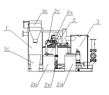
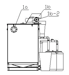
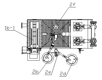
[0033] see Figure 1 to Figure 3 , a fully automatic oil-separating and lifting integrated equipment provided by the present invention, comprising a connected debris separation box 1, an oil-water separation box 2 and a sewage lifting box 3, one side of the debris separation box 1 passes through the water inlet assembly 1a is connected to the waste water inlet pipeline, and the water inlet in the debris separation box 1 is provided with a mechanical grille 1b, see figure 2 , image 3 , the mechanical grille 1b is composed of an inclined conveyor belt 1b-1 inserted obliquely into the debris separation box 1, and a motor 1b-2 that provides power for the conveyor belt. The outer surface of the inclined conveyor belt 1b-1 Several groups of drag hooks are evenly distributed, and the insertion end of the inclined conveyor belt 1b-1 is in contact with the inner wall of the debris separation box 1. After the waste water enters, the motor 1b-2 drives the inclined conveyor belt 1b-1 t...

Embodiment 2

[0036] The difference between this embodiment and Embodiment 1 is that in order to prevent the oil in the oil-water separation box 2 from solidifying and cannot be discharged, a heating device 2f is arranged on the oil-water separation box 2 to heat the oil that may solidify. The heating device 2f includes an electric heating rod installed in the oil-water separation tank 2 and a heating blanket laid on the body of the oil-water separation tank 2 .


PUM


Abstract

The present invention discloses a full-automatic oil separation lifting integrated device, including a debris separation tank, an oil-water separation tank and a sewage lifting tank which are communicated. The debris separation tank is connected with a sewage inlet pipe. The water inlet of the debris separation tank is provided with a mechanical grid which can automatically remove solid debris. The top of the oil-water separation tank is provided with an automatic oil wiper. The automatic oil wiper is communicated with an oil collection barrel. The bottom end of the oil-water separation tank is provided with a mud collection barrel communicated with the oil-water separation tank. The integrated device is compact in structure, saves civil construction, has the functions of efficient oil separation, automatic debris clearing, efficient mud discharging and automatic sewage lifting and discharging, and has the advantages of environmental protection, health, energy conservation, and small space occupation.

Description

technical field [0001] The invention belongs to the technical field of sewage treatment equipment, and in particular relates to a fully automatic oil separation and lifting integrated equipment with oil separation, slag removal, mud discharge and lifting devices. Background technique [0002] At present, with the acceleration of urbanization and the increasing shortage of land resources, the utilization rate of underground space resources is getting higher and higher. In daily life, the frequency of use of underground kitchens is also increasing, and the problems of wastewater treatment and sewage discharge in underground kitchens are also becoming more and more prominent. Kitchen wastewater discharge is different from ordinary sewage discharge. First, oil-water separation is required, and sundries and sludge need to be removed. Sewage discharge also needs to meet the requirements of the "Water Quality Standards for Urban Sewage Discharge into Sewers". Otherwise, the dr...

Claims


Application Information

Patent Timeline
Patent Type & Authority Applications(China)
IPC IPC(8): C02F9/02
Inventor 李文兵王玉峰汤威孟健李光增孟维俊
Owner ANHUI TIANJIAN ENVIRONMENTAL PROTECTION
Why Eureka
Try Eureka