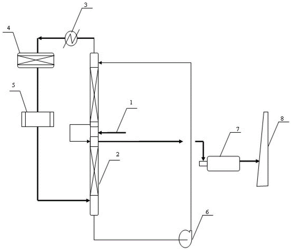
Liquid-phase treatment process of tail gas from sulfur recovery
A sulfur recovery tail gas and treatment process technology, applied in the direction of sulfur preparation/purification, can solve the problems of high operating costs and energy consumption, low total sulfur recovery rate, large construction investment, etc., to achieve reduced operating costs, and energy consumption Effect of reducing and increasing sulfur recovery rate
- Summary
- Abstract
- Description
- Claims
- Application Information
AI Technical Summary
Problems solved by technology
Method used
Image
Examples
Embodiment 1
[0039] The sulfur production tail gas is generated after the acid gas recovers sulfur through the Claus sulfur recovery unit; the molar ratio of hydrogen sulfide and sulfur dioxide is controlled at 3:1, and the sulfur production tail gas enters the water film reactor, and the temperature of the reactor is controlled at 160±3°C. The reaction produces sulfur, producing H 2 S tail gas; contains H 2 S tail gas is in direct contact with water to cool down, and the condensed process wastewater is discharged to the outside; 2 S tail gas is heated to 190±3°C and enters the oxidation reactor for oxidation to produce process gas; the process gas enters the sulfur cooler for cooling, and then enters the water film reactor for further reaction, the temperature of the water film reactor is controlled at 160±3°C; the waste gas is incinerated rear discharge. The sulfur recovery rate is 99.98%.
Embodiment 2
[0041] The sulfur production tail gas is produced after the acid gas recovers sulfur through the Claus sulfur recovery unit; the molar ratio of hydrogen sulfide and sulfur dioxide is controlled at 4:1, and the sulfur production tail gas enters the water film reactor, and the temperature of the reactor is controlled at 170±3°C. The reaction produces sulfur, producing H 2 S tail gas; contains H 2 S tail gas is in direct contact with water to cool down, and the condensed process wastewater is discharged to the outside; 2 S tail gas is heated to 210±3°C and enters the oxidation reactor for oxidation to produce process gas; the process gas enters the sulfur cooler for cooling, and then enters the water film reactor for further reaction, the temperature of the water film reactor is controlled at 170±3°C; the waste gas is incinerated rear discharge. The sulfur recovery rate is 99.99%.
Embodiment 3
[0043]The sulfur production tail gas is generated after the acid gas recovers sulfur through the Claus sulfur recovery unit; the molar ratio of hydrogen sulfide and sulfur dioxide is controlled at 3:1, and the sulfur production tail gas enters the water film reactor, and the temperature of the reactor is controlled at 165±3°C. The reaction produces sulfur, producing H 2 S tail gas; contains H 2 S tail gas is in direct contact with water to cool down, and the condensed process wastewater is discharged to the outside; 2 S tail gas is heated to 200±3°C and enters the oxidation reactor for oxidation to produce process gas; the process gas enters the sulfur cooler for cooling, and then enters the water film reactor for further reaction, the temperature of the water film reactor is controlled at 165±3°C; the waste gas is incinerated rear discharge. The sulfur recovery rate is 99.98%.
PUM
 Abstract
Description
Claims
Application Information
 - R&D
- Intellectual Property
- Life Sciences
- Materials
- Tech Scout
- Unparalleled Data Quality
- Higher Quality Content
- 60% Fewer Hallucinations
Browse by: Latest US Patents, China's latest patents, Technical Efficacy Thesaurus, Application Domain, Technology Topic, Popular Technical Reports.
© 2025 PatSnap. All rights reserved.Legal|Privacy policy|Modern Slavery Act Transparency Statement|Sitemap|About US| Contact US: help@patsnap.com


