
Planetary motion grinding device

A grinding device, motion-type technology, applied in the direction of grinding devices, grinding machine tools, metal processing equipment, etc., can solve the problem of reducing the stability of revolution motion and system dynamic stiffness, reducing the sensitivity of axial reciprocating motion of the rotation axis, and reducing the stability of the removal function And other problems, to achieve the effect of improving rotational symmetry, improving motion sensitivity, and reducing friction

Inactive Publication Date: 2013-02-27
INST OF OPTICS & ELECTRONICS - CHINESE ACAD OF SCI
View PDF8 Cites 9 Cited by
  • Summary
  • Abstract
  • Description
  • Claims
  • Application Information

AI Technical Summary

Problems solved by technology

The axial reciprocating motion of the rotation shaft of the planetary wheel type CNC grinding and polishing removal function generator adopts sliding series motion, and the sliding friction resistance of the reciprocating motion is affected by the transmission torque and the roughness of the contact surface. Reduced reciprocating sensitivity, which reduces the stability of the removal function
In addition, the strict translation of the rotation shaft system during the revolution process is constrained by two sets of vertically arranged swing rods. The swing rods are hinged with the transition plate, the retaining seat, and the slewing seat to ensure the translation of the slewing seat during the revolution movement. Supporting gravity, asymmetric restraint force, reducing the stability of revolution motion and dynamic stiffness of the system

Method used


Image

  • Planetary motion grinding device
  • Planetary motion grinding device
  • Planetary motion grinding device

Examples


Embodiment Construction

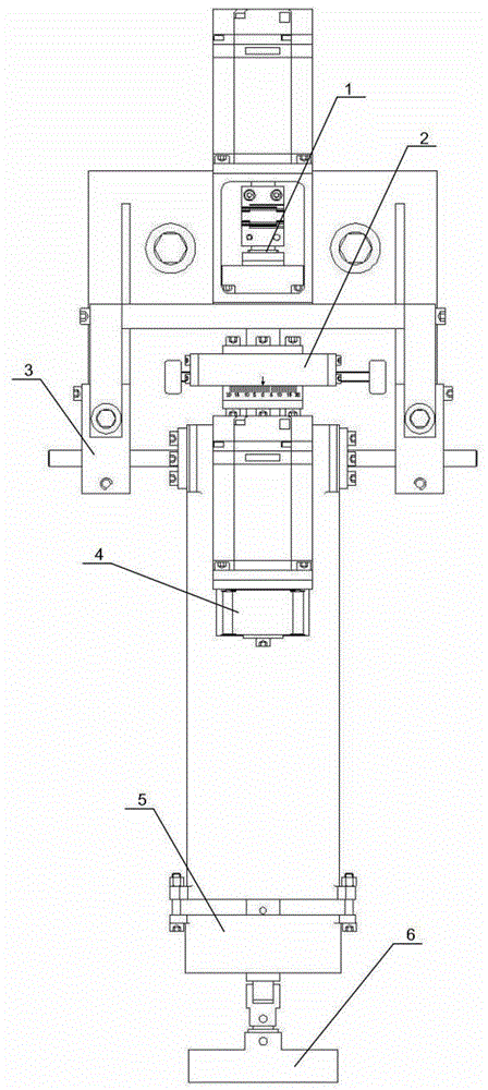
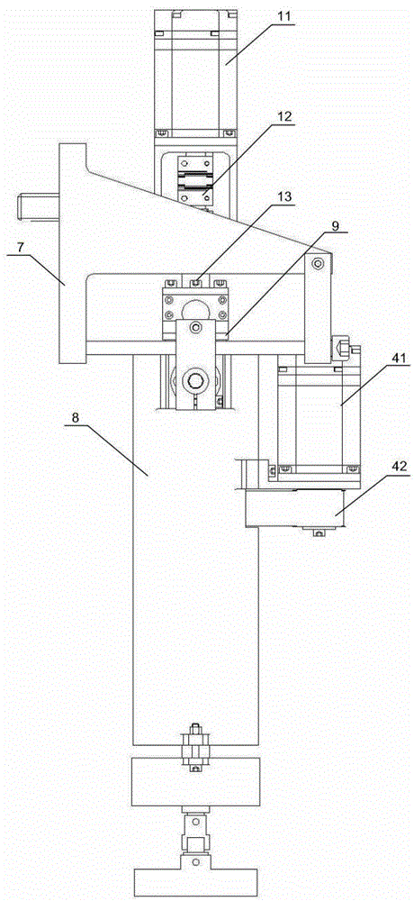
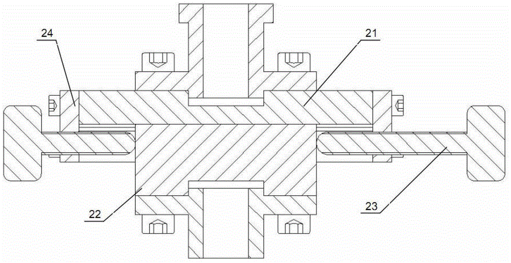
[0025] Such as Figures 1 to 9 As shown, a planetary motion grinding device of the present invention includes a revolution mechanism 1, an eccentric adjustment mechanism 2, a translation holding mechanism 3, an autorotation mechanism 4, a pressure applying mechanism 5, a grinding disc mechanism 6, an interface panel 7, and a main seat Body 8, rotary mechanism 9. The revolution mechanism 1 is connected to the interface panel 7, the eccentric adjustment mechanism 2 is connected to the lower end of the revolution mechanism 1, and the flange of the revolution shaft system 13, and the translation holding mechanism 3 is located outside the eccentric adjustment mechanism 2, and is connected to the interface panel 7 and the main body 8, the rotary mechanism 9 is connected to the lower end of the eccentric adjustment mechanism 2, on the lower dovetail 22, located in the main base body 8, the autorotation mechanism 4 is located below the rotary mechanism 9, connected to the main base bo...


PUM


Abstract

The invention discloses a planetary motion grinding device, and belongs to the technical field of manufacturing of precision machinery. The invention aims to overcome the defects of the existing mechanical grinding technology, and provide the grinding device capable of removing quantitative materials, stably running, and removing the function stability. The grinding device comprises an interface panel, a revolution mechanism, an eccentric adjusting mechanism, a main seat body, a translation keeping mechanism, a swing mechanism, a rotating mechanism, a pressure applying mechanism and a grinding disc mechanism; the revolution mechanism provides revolution movement; the rotating mechanism provides rotation movement and axial free flotation of a grinding disc; the eccentric adjusting mechanism realizes adjustment on the revolution radius; the translation keeping mechanism ensures that the main seat body, the swing mechanism, the rotating mechanism, the pressure applying mechanism and the grinding disc mechanism stably move in the revolution movement, and assists a support device in gravity; the pressure applying mechanism is used for applying grinding pressure; and the grinding disc mechanism can ensure that the grinding disc can incline at a small angle in any direction.

Description

technical field [0001] The invention belongs to the technical field of precision machinery manufacturing, and in particular relates to a grinding device used for mechanical grinding and obtaining high machining accuracy. Background technique [0002] In mechanical processing, grinding technology has developed rapidly. From traditional manual grinding, various types of grinding machines have been developed, which have replaced manual labor to a certain extent and met the grinding requirements of small and medium-sized parts. Like manual grinding, it is qualitative grinding. For large and heavy parts and large planes, the finishing of such parts still adopts the traditional processing idea. After the rough machining and semi-finishing of large-scale equipment, the finishing is completed by manual local repairing. Because it is a qualitative correction , there are blindness and human factors, the accuracy is difficult to improve. Quantitative grinding technology has been well...

Claims


Application Information

Patent Timeline
IPC IPC(8): B24B37/00B24B37/34
Inventor 安祥波余伦涂文英钱静
Owner INST OF OPTICS & ELECTRONICS - CHINESE ACAD OF SCI
Learn More