
System and method for achieving accurate positioning of off-axis aspheric surface reflector

A precise positioning, aspheric technology, used in optics, optical components, installation and other directions, can solve the problems of inability to achieve effective positioning of off-axis optics, off-axis optical components, many adjustment variables, and inability to achieve effective assembly and adjustment.

Inactive Publication Date: 2013-02-20
XI'AN INST OF OPTICS & FINE MECHANICS - CHINESE ACAD OF SCI
View PDF5 Cites 26 Cited by
  • Summary
  • Abstract
  • Description
  • Claims
  • Application Information

AI Technical Summary

Problems solved by technology

For the off-axis optical system, due to the particularity of the system design, that is, the optical elements in the optical system do not have a common optical axis, and because the off-axis optical element does not have the central part of the optical axis, it cannot be realized by conventional adjustment methods. Efficient tuning of such systems
In addition, due to the large number of optical elements in the off-axis optical system, there are too many adjustment variables when the system is assisted by the method of computer-aided adjustment, which reduces the effectiveness of the adjustment and cannot achieve the effective effect of each off-axis optical element in the off-axis optics. position
In addition, the off-axis spherical mirror has a unique radius of curvature, so it is easier to locate the center of the radius of curvature; while the center of the radius of curvature of the off-axis aspheric mirror is not unique, the line connecting the centers of multiple curvature radii of the aspheric surface as its Optical axis, when the system is installed and adjusted, it is necessary to accurately determine the optical axis position of each aspheric mirror to ensure the good imaging quality of the system, so it is more difficult to accurately locate the optical axis of the off-axis aspheric mirror

Method used


Image

  • System and method for achieving accurate positioning of off-axis aspheric surface reflector
  • System and method for achieving accurate positioning of off-axis aspheric surface reflector
  • System and method for achieving accurate positioning of off-axis aspheric surface reflector

Examples


Embodiment Construction

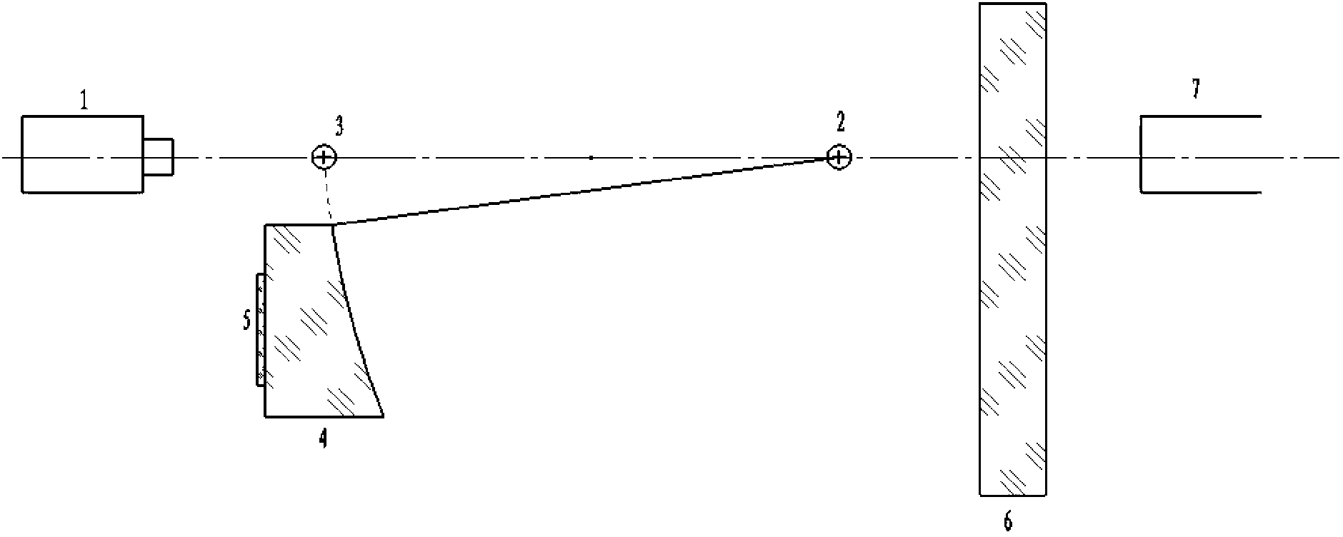
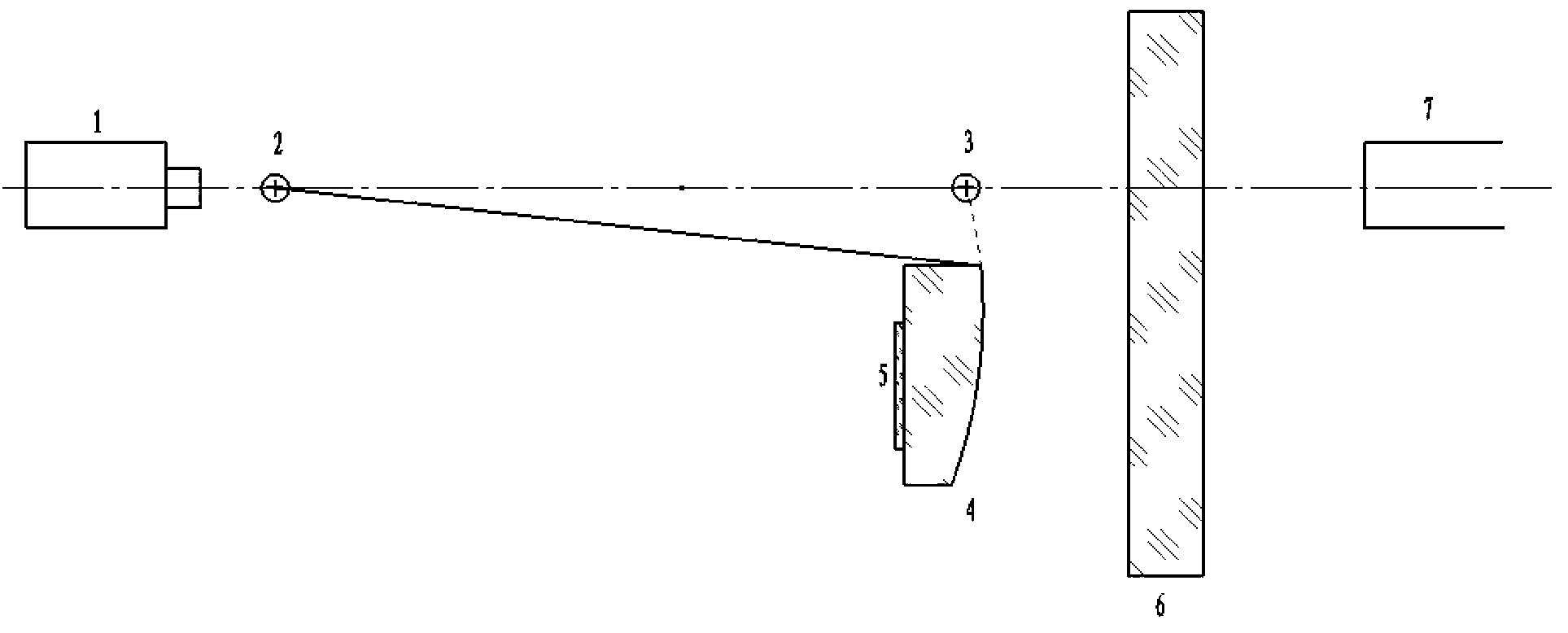
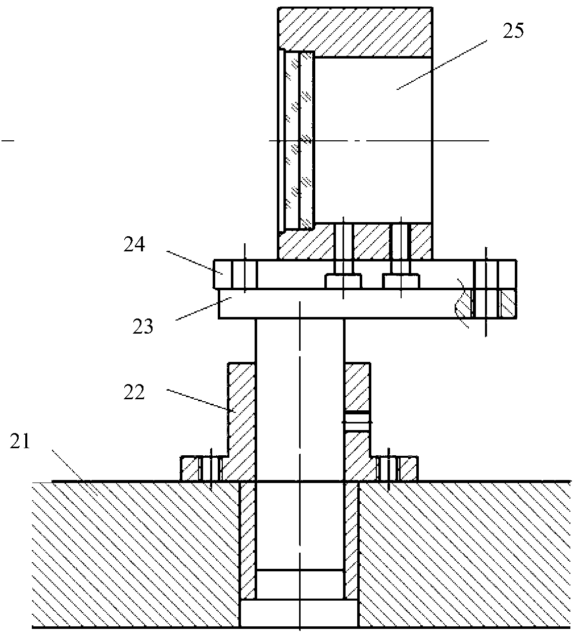
[0028] see image 3 , the present invention provides a system for realizing precise positioning of the optical axis of an off-axis aspheric mirror, the system comprising an autocollimation theodolite 1, a radius of curvature center positioning tool for determining the center position of the radius of curvature of the aspheric mirror to be positioned 2. Apex center positioning tooling 3 for determining the position of the apex center of the aspheric mirror 4 to be positioned, a large-aperture plane mirror 6, an internal focusing telescope 7, and a flat plate attached to the back of the aspheric mirror to be positioned Glass 5; the self-collimating theodolite, the radius of curvature center positioning tool, the apex center positioning tool, the large-diameter plane mirror and the inner focusing telescope are sequentially arranged on the same optical axis. Both the curvature radius center positioning tool and the apex center positioning tool include a high-precision flat plate, ...


PUM


Abstract

The invention relates to a system and method for achieving accurate positioning of an off-axis aspheric surface reflector. The system comprises an auto-collimation theodolite, a curvature radius center positioning tool for determining the center position of a curvature radius of an aspheric surface reflector to be positioned, a peak center positioning tool for determining the center position of the peak of the aspheric surface reflector to be positioned, a large diameter plane reflector, an internal focusing telescope and sheet glass attached to the back face of the aspheric surface reflector to be positioned. The auto-collimation theodolite, the curvature radius center positioning tool, the peak center positioning tool, the large diameter plane reflector and the internal focusing telescope are arranged on the same optical axis in sequence. The system and method for achieving accurate positioning of the off-axis aspheric surface reflector is high in positioning accuracy, easy to adjust and convenient to use.

Description

technical field [0001] The invention belongs to the field of optical precision assembly and adjustment, and relates to a precise positioning system and method for the optical axis of a reflector, in particular to a system and method for realizing precise positioning of the optical axis of an off-axis aspheric reflector. Background technique [0002] With its unique advantages, aspheric mirrors have been used in coaxial optical systems, off-axis optical systems, and now off-axis optical systems. For the off-axis optical system, due to the particularity of the system design, that is, the optical elements in the optical system do not have a common optical axis, and because the off-axis optical element does not have the central part of the optical axis, it cannot be realized by the conventional adjustment method in the past. Efficient setup of such systems. In addition, due to the large number of optical components in the off-axis optical system, there are too many adjustment v...

Claims


Application Information

Patent Timeline
IPC IPC(8): G02B7/182G02B27/32
Inventor 张学敏魏儒义侯晓华李智勇段嘉友李华
Owner XI'AN INST OF OPTICS & FINE MECHANICS - CHINESE ACAD OF SCI
Learn More