
Oil-immersed capacitive voltage divider

A capacitive voltage divider, oil-immersed technology, applied in the direction of voltage divider, can solve the problems of easy generation of parasitic coupling, uneven electric field, increase in volume, etc., and achieve the effect of reducing interference, high precision and small error

Inactive Publication Date: 2013-02-20
WUHU KEWEI MEV ELECTRONICS
View PDF0 Cites 2 Cited by
  • Summary
  • Abstract
  • Description
  • Claims
  • Application Information

AI Technical Summary

Problems solved by technology

Usually potting type resistance-capacitance divider is used, although it can meet the requirements of withstand voltage and precision, but the higher the voltage, the heat generated by it will also increase, and the volume will increase accordingly. , such as laboratories, testing rooms, etc., you can use a capacitive voltage divider. The conventional capacitive voltage divider uses a strip transmission line. Due to the boundary of the strip line, the electric field is not uniform, and it is easy to generate parasitic coupling.

Method used


Image

  • Oil-immersed capacitive voltage divider

Examples


Embodiment Construction

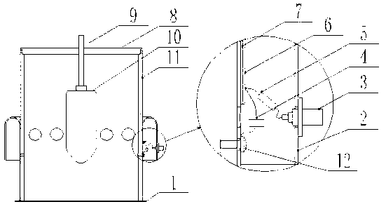
[0011] Such as figure 1 As shown, an oil-immersed capacitive voltage divider includes a box body, a cover plate 8, a base plate 1, and an insulating shell 11 arranged on the base plate 1. The insulating shell 11 is provided with a shielding shell 2. The described The insulating shell 11 in the shielding shell 2 is provided with a capacitor plate 6, an insulating layer 7 is provided between the insulating shell 11 and the capacitor plate 6, and a BNC seat 3 is provided on the shielding shell 2, and the BNC seat 3 passes through the current limiting The protection resistor 5 is connected to the capacitor plate 6 , and the capacitor plate 6 is connected to the shielding shell 2 through the voltage dividing sampling capacitor 4 .

[0012] The voltage-dividing sampling capacitor 4 is susceptible to interference, and when it is disturbed, it has a great influence on the sampling signal, causing a large deviation between the sampling value and the actual value. Therefore, the shieldi...


PUM


Abstract

An oil-immersed capacitive voltage divider comprises a case, a cover plate, a base plate and an insulated casing which is arranged on the base board. A shielding casing is arranged on the insulated casing, a capacitor polar plate is arranged on the insulated casing and inside the shielding casing, and an insulated layer is arranged between the insulated casing and the capacitor polar plate. A bayonet nut connector (BAC) base is arranged on the shielding casing and connected with the capacitor polar plate through a current limiting protection resistor. The capacitor polar plate is connected with the shielding casing through a voltage dividing sampling capacitor. The signal output is connected through the shielding casing, so that the accuracy of sampling signals is guaranteed, the dismounting is facilitated, interference to the capacitive voltage divider in severe electromagnetic environments is reduced, voltages are measured accurately, and performances deserved by the capacitive voltage divider can be met. The capacitive voltage divider is high in accuracy, small in error and attractive in appearance.

Description

Technical field: [0001] The invention relates to an oil-immersed capacitor voltage divider. Background technique: [0002] At present, with the development of science and technology, the application of voltage dividers is becoming more and more common, and various types of voltage dividers have emerged with different uses. Its performance is more reliable and its precision is higher. Working under harsh conditions, such as vehicle vibration, high altitude, and severe cold environments. Usually potting type resistance-capacitance divider is used, although it can meet the requirements of withstand voltage and precision, but the higher the voltage, the heat generated by it will also increase, and the volume will increase accordingly. , such as laboratories, testing rooms, etc., you can use a capacitive voltage divider. The conventional capacitive voltage divider uses a strip transmission line. Due to the boundary of the strip line, the electric field is not uniform, and it is...

Claims


Application Information

Patent Timeline
Patent Type & Authority Applications(China)
IPC IPC(8): G01R15/06
Inventor 李成聂玉春王文娟吴登科
Owner WUHU KEWEI MEV ELECTRONICS
Learn More