
Nailless binding device

A staple-free bookbinding and bookbinding machine technology, applied in directions such as bookbinding, can solve the problems of affecting the positioning accuracy of the slicing device 51 and the notch blade 52, the bookbinding quality, the needle tip lifting, affecting the cutting accuracy, etc., so as to improve the bookbinding accuracy and the binding quality, Reduce the fit gap and ensure the effect of accurate positioning

Inactive Publication Date: 2013-02-20
徐静波
View PDF1 Cites 3 Cited by
  • Summary
  • Abstract
  • Description
  • Claims
  • Application Information

AI Technical Summary

Problems solved by technology

[0005] 1. Since the staple is made of metal, when it passes through the paper and is bent, the needle point is prone to warping, which often scratches the user or other paper
[0006] 2. Since staples are made of metal, they are prone to oxidation and rust after binding, which will stain the paper and affect the overall appearance of paper documents
[0007] 3. Since the staples will remain on the paper after binding the paper, when the paper needs to be reused (such as secondary printing of single-sided waste paper), or when important paper documents need to be destroyed (such as using shredded paper The machine shreds the paper), the staples left on the paper will affect the normal operation, and in severe cases, it will damage other office equipment such as printers or paper shredders, so it is necessary to manually remove the staples, and then do the second One time use, but time-consuming and labor-intensive
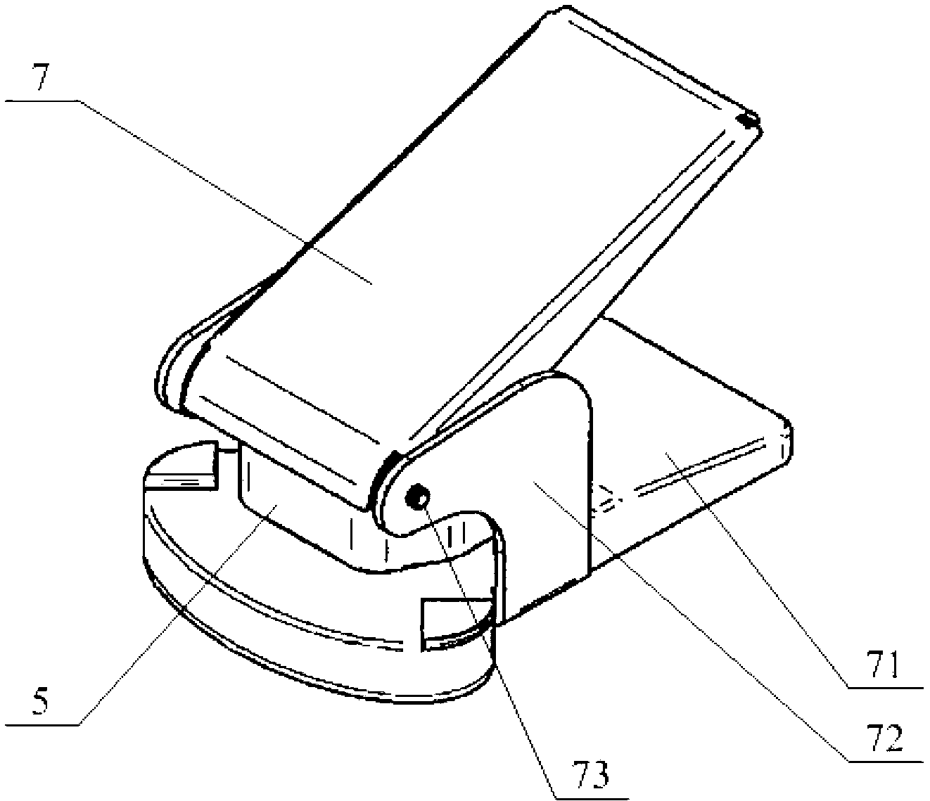
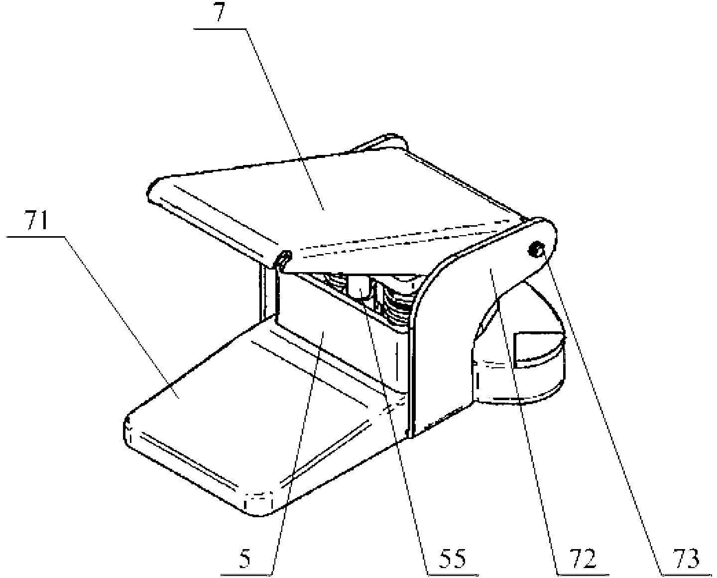
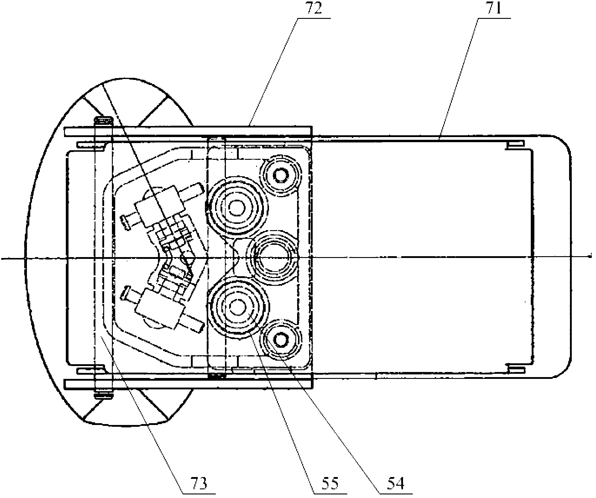
[0009] But this stapleless stapler, because it finishes binding, is to drive slicing device 51 and otch blade 52 to move by the sliding inside binding machine 5, thereby finishes cutting paper 6; But binding machine 5 slips when happening Simultaneously, a certain offset will occur, and this offset will directly affect the cutting accuracy of the slicing device 51 and the kerf blade 52 to the paper 6, thereby affecting the positioning accuracy and final binding quality of the slicing device 51 and the kerf blade 52; In order to avoid that the binding machine 5 is offset while sliding, as figure 2 and image 3 As shown, it is provided with a positioning device in the binding machine 5, and the positioning device includes a guide post 54 and a cylindrical portion 55, and the guide post 54 is placed in the cylindrical portion 55, and the guide post 54 is used to slide in the cylindrical portion 55, thereby Accurate positioning of the slicing device 51 and the kerf blade 52 is realized in the binding process, but the structure of the guide post 54 and the barrel 55 is adopted, and there is a certain fit gap between the two, so it is difficult to realize accurate positioning, so it is difficult to improve Binding accuracy and quality of binding machine 5

Method used


Image

  • Nailless binding device
  • Nailless binding device
  • Nailless binding device

Examples


Embodiment Construction

[0067] In order to make the purpose, technical solution and advantages of the present invention clearer, the technical solution of the present invention will be clearly and completely described below. All other implementations obtained below fall within the protection scope of the present invention.

[0068] Before describing the specific implementation, it is stipulated that the binding position on the stapler is the front end, and the operating part of the handle is the rear end (it can also be regarded as the gripping part of the handle); and the direction of the line from the front end to the rear end is defined as the longitudinal direction .

[0069] Such as Figures 8 to 11 As shown, the staple-free stapler provided by the embodiment of the present invention includes a handle 1, an abutment 2 and a binding machine 3, and the two sides of the abutment 2 along the longitudinal direction are provided with support plates 21, and the front ends of the handle 1 are placed on...


PUM


Abstract

The invention provides a nailless binding device. The nailless binding device comprises a handle, a base platform and a binding machine, two sides along the longitudinal direction of the base platform are respectively provided with a supporting plate, the front end of the handle is arranged between the two supporting plates and hinged with the two supporting plate through a rotating shaft, a slicing device and a notch blade are arranged in the binding machine, and the bottom of the binding machine is fixedly connected with the base platform. A positioning device is arranged in the binding machine and comprises a guide block and a guide groove which are mutually matched, and the cross sections of the guide block and the guide groove are both trapezoid. The nailless binding device completes nailless binding through the handle, the base platform and the binding machine, the guide block and the guide groove which are arranged in the binding machine and both have trapezoid cross sections can perform the positioning function on the binding machine, relative sliding of the guide block and the guide groove is guaranteed, a matching gap between the guide block and the guide groove is simultaneously reduced as far as possible, the fact that sliding and displacement of the binding machine at the same time is avoided, accordingly accurate positioning of the binding machine is guaranteed, and binding accuracy and binding quality are improved.

Description

technical field [0001] The invention relates to an office product, in particular to a staple-free binder. Background technique [0002] In daily work, staplers are an indispensable part of office supplies. [0003] At present, the staplers we use generally use the stapler body to squeeze the staples through the paper, and then bend the staples, so as to achieve the purpose of binding the papers, which can realize fast binding and facilitate operation, so it is widely used by people. [0004] However, with the use of staplers, some disadvantages of staplers have gradually emerged, mainly including the following points: [0005] 1. Since the staple is made of metal, when it passes through the paper and is bent, the tip of the staple tends to warp, which often scratches the user or other paper. [0006] 2. Since the staple is made of metal, it is prone to oxidation and rust after binding, which will stain the paper and affect the overall appearance of the paper document. ...

Claims


Application Information

Patent Timeline
Patent Type & Authority Applications(China)
IPC IPC(8): B42B5/00
Inventor 徐静波
Owner 徐静波
Learn More