
Electronic current transformer

A current transformer, electronic technology, applied in the direction of voltage/current isolation, etc., can solve the problems of poor stability, poor anti-interference, and needs to be improved, and achieve the effect of good linearity and wide measurement range

Inactive Publication Date: 2013-02-13
NANJING JIANGBEI AUTOMATION TECH
View PDF6 Cites 6 Cited by
  • Summary
  • Abstract
  • Description
  • Claims
  • Application Information

AI Technical Summary

Problems solved by technology

Although the electronic transformer has the advantages of insulation and other aspects, there is still a certain gap compared with the traditional electromagnetic measurement method in terms of reliability, stability and accuracy, which needs to be improved
Especially its important component, as the sensor Rogowski coil for primary current collection, has always had many problems such as poor anti-interference and poor stability since the beginning of research at home and abroad, making it difficult for electronic transformers to be popularized in a large area. Form industrialization

Method used


Image

  • Electronic current transformer
  • Electronic current transformer

Examples


Embodiment Construction

[0010] The present invention will be described in further detail below in conjunction with the accompanying drawings.

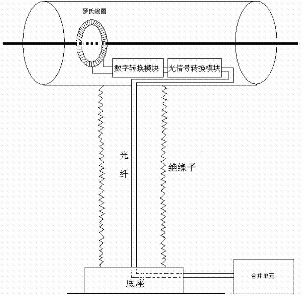
[0011] figure 1 It is an existing Rogowski coil current transformer and a using method.

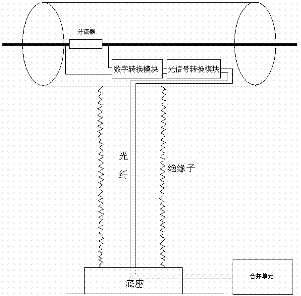
[0012] figure 2 It is the electronic current transformer of the present invention and the method of use: the electronic current transformer is characterized in that it includes a shunt, a digital conversion module, an optical signal conversion module and a transformer merging unit; wherein:

[0013] The digital conversion module is used to convert the analog signal into a digital signal, and the optical signal conversion module is used to convert the electrical signal into an optical signal; the two ends of the shunt are connected to the two input terminals of the digital conversion module; the two output terminals of the digital conversion module are connected to the optical signal The two input terminals of the signal conversion module, the optical signal output by ...


PUM


Abstract

The invention discloses an electronic current transformer which comprises a shunt, a digital conversion module, an optical signal conversion module and a mutual inductor combining unit, wherein the digital conversion module is used for converting simulation signals into digital signals, and the optical signal conversion module is used for converting electrical signals into optical signals; two ends of the shunt are respectively connected with two input ends of the digital conversion module; and two output ends of the digital conversion module are connected with two input ends of the optical signal conversion module, and the optical signals output by the optical signal conversion module are input to the mutual inductor combining unit. The current transformer is good in linearity, real and reliable in transmission and conversion performance, free of wave distortion phenomenon, magnetic saturation phenomenon and trailing phenomenon, strong in anti-interference performance, wide in measuring range and capable of performing testing from several amperes to several kiloamperes.

Description

technical field [0001] The invention belongs to the technical field of electric power system current detection, and in particular relates to an electronic current transformer. Background technique [0002] The current and voltage transformer is an indispensable and important equipment in the power system. Its function is to reduce the high voltage and large current on the transmission line to the standard value that can be directly measured by the instrument, so that the instrument can be used for direct measurement. Traditional power transformers (ie, CT, PT) have defects such as poor electrical insulation performance, small dynamic range, and saturation. The electronic current and voltage transformers (i.e. ECT, EPT) developed in recent years adopt a new sensing principle, which can effectively overcome the defects of traditional power transformers, and provide a good solution for the safe operation of power systems, cost savings, and optimization of secondary equipment. ...

Claims


Application Information

Patent Timeline
Patent Type & Authority Applications(China)
IPC IPC(8): G01R15/18
Inventor 赵晶晶
Owner NANJING JIANGBEI AUTOMATION TECH
Learn More