
Device and method for detecting synchronous control system of attached lifting scaffold

A technology of synchronous control and attached lifting, which is applied in the direction of measuring devices, scaffolding supported by building structures, and measuring forces, can solve problems such as difficult to achieve reliable use standards, increase unsafe hidden dangers, and large volume of tensile sensors. Simple, avoid height difference out of sync, improve sensitivity and accuracy

Active Publication Date: 2015-07-15
苏茂兵
View PDF7 Cites 0 Cited by
  • Summary
  • Abstract
  • Description
  • Claims
  • Application Information

AI Technical Summary

Problems solved by technology

Therefore, the new devices or structures such as sensors added to the lifting load chain not only need to pass the national special equipment production certification before they can be used, but no matter their own structure or the connection with other structural components, they undoubtedly add new features. unsafe hidden dangers
Therefore, although the tensile sensors currently used to limit the synchronous control system attached to the lifting scaffold load are usually large in size and high in cost, the actual effect is still difficult to meet the reliable use standard in actual construction

Method used


Image

  • Device and method for detecting synchronous control system of attached lifting scaffold
  • Device and method for detecting synchronous control system of attached lifting scaffold
  • Device and method for detecting synchronous control system of attached lifting scaffold

Examples


Embodiment Construction

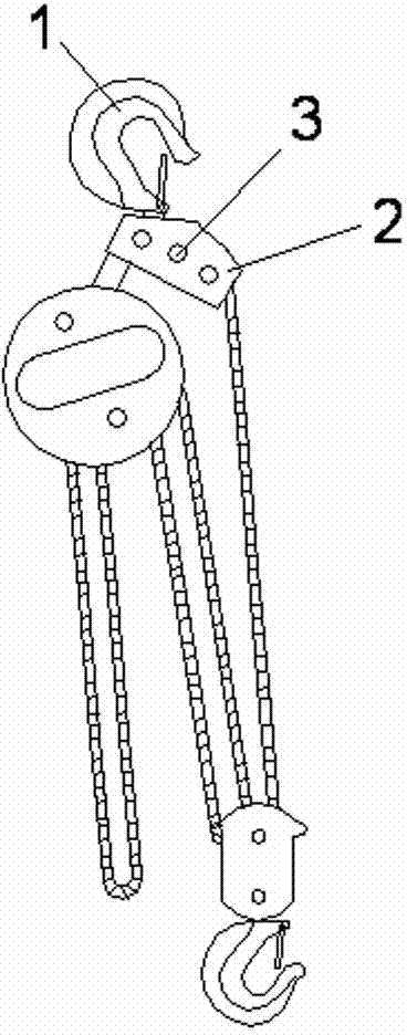
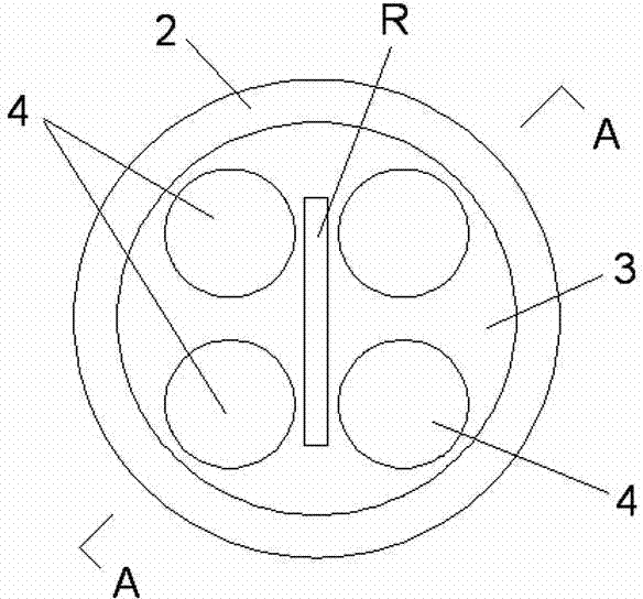
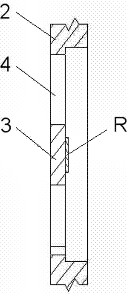
[0027] Figure 1~Figure 4 The detection device of the present invention attached to the synchronous control system of the lifting scaffolding shown in the present invention is to set a hole bottom thickness of 0.5~6mm on the force bearing part 2 of the lifting load force of the lifting structure 1 such as the base plate of the lifting hook. The bottom plate is an elastically deformable area 3, and a number of small through holes 4 (four in the figure) are opened in the elastically deformable area 3 at intervals. On the surface of the elastically deformable region 3, a strain resistance structure R that can deform synchronously with the deformation of the part subjected to gravity and is powered by an independent power supply U is bonded in a manner of electrical insulation and surface contact with it. The strain resistance structure R is connected with the PLC control mechanism attached to the synchronous control system of the lifting scaffold at the same time. The strain res...


PUM


Abstract

A device and a method for detecting a synchronous control system of an attached lifting scaffold are provided. At least one strain resistance structure is arranged at a force bearing position of hoisting load power of a hoisting lifting structure in a mode that the strain resistance structure is electrically insulated with the hoisting lifting structure, can deform synchronously with the deformation of the position due to gravity, and is provided with power supplied by an independent power source. The strain resistance structure is connected with a programmable logic controller (PLC) of the synchronous control system of the attached lifting scaffold simultaneously. The PLC respectively sets voltage or current signals at two ends of the strain resistance structure to be an original value and a detection standard under the condition that the hoisting lifting structure is under empty load and normal load, and increase and decrease of the current or voltage of the strain resistance structure during the operation of the hoisting lifting structure are compared with a preset range, so that whether the overload or empty load of the hoisting lifting structure happens during ascending or descending operation, especially during the descending can be timely detected, accident hazards caused by asynchronous heights of lifting positions of the attached lifting scaffold are avoided, and active safety protection on the operation of the attached lifting scaffold is achieved.

Description

technical field [0001] The invention relates to a detection device and method for controlling a synchronous lifting operation system of an attached lifting scaffold. Background technique [0002] Attached lifting scaffolding is a high-altitude suspended scaffolding that is set up at a certain height along the outside of the building and around the building during construction. Through the joint operation of the lifting equipment set at intervals, it can be used as a piece or as a whole at the same time. Lifting and moving to meet construction needs. Since the perimeter of the building in the actual project can reach hundreds of meters, and the shape of the building is also varied due to different design schemes (such as balconies, air-conditioning panels, convex and concave corners, etc.), the distance between adjacent lifting equipment positions can vary. There is a difference of 1~7 meters. The number of hoisting and lifting equipment used in each construction project ca...

Claims


Application Information

Patent Timeline
Patent Type & Authority Patents(China)
IPC IPC(8): G01L1/22E04G3/32
Inventor 苏茂兵苏波
Owner 苏茂兵
Learn More