
Method for controlling flow fields in quenching water tank of large cylindrical workpiece

A technology for large cylinders and workpieces is applied in the field of flow field regulation in quenching water tanks, which can solve the problems of poor circulation performance of quenching medium, poor practical applicability and difficulty, and achieve good operability and ensure the effect of quenching quality.

Inactive Publication Date: 2013-02-13
SHANGHAI DIANJI UNIV
View PDF2 Cites 7 Cited by
  • Summary
  • Abstract
  • Description
  • Claims
  • Application Information

AI Technical Summary

Problems solved by technology

However, only a small part of the quenching medium participates in the quenching and cooling work during quenching, and the circulation performance of the quenching medium in the entire quenching tank is poor, and the cooling performance of the quenching tank cannot be fully utilized.
In addition, in actual production, the quenching of large workpieces is mainly carried out by using a crane to immerse the workpieces into the quenching water tank. It is difficult for workers to ensure that the position of the workpieces matches the position of the flow opening on the restrictor plate at the bottom of the quenching tank during operation. Applicability is also poor

Method used


Image

  • Method for controlling flow fields in quenching water tank of large cylindrical workpiece

Examples


Embodiment Construction

[0014] In order to illustrate the technical content, structural features, achieved goals and effects of the present invention in detail, the following will be described in detail in conjunction with the embodiments and accompanying drawings.

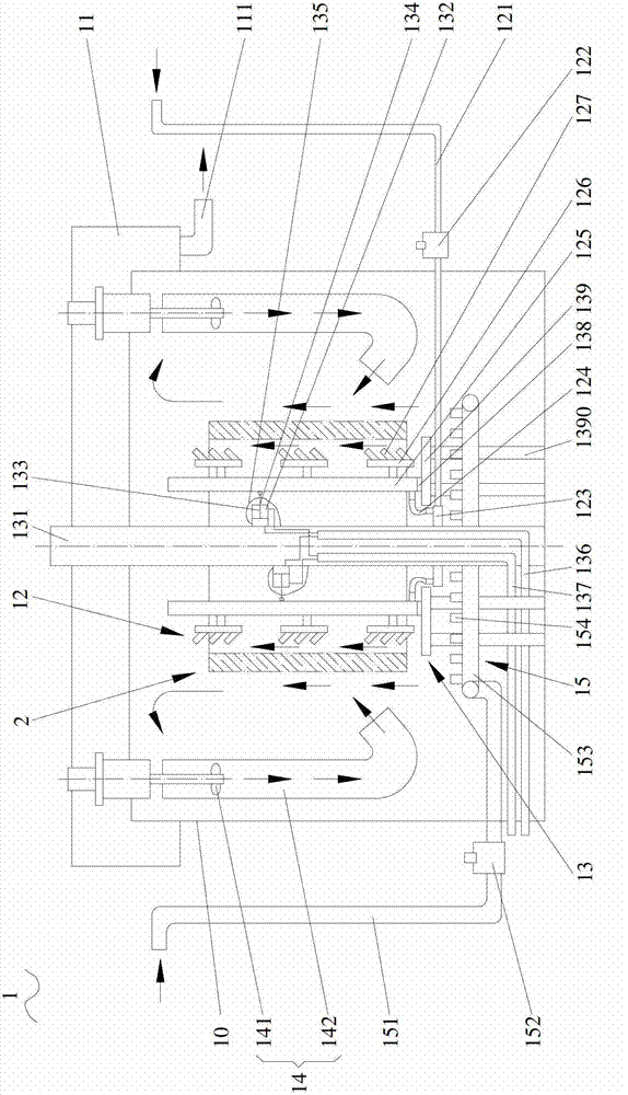
[0015] see figure 1 , figure 1 It is a schematic diagram of the flow field control method in the quenching water tank of a large cylindrical workpiece of the present invention, including a quenching water tank 1 and a large cylindrical workpiece 2 . The large cylindrical workpiece 2 can be hoisted by a crane and placed in the quenching water tank 1 for quenching operation. The quenching water tank 1 includes a tank body 10, an overflow tank 11, an overflow pipe 111, an inner nozzle jet device 12, an inner nozzle diameter adjustment device 13, a propeller agitating jet device 14, and an outer nozzle jet device 15. The overflow tank 11 has an overflow pipe 111 and is arranged on the upper end of the tank body 10 .

[0016] The quenching...


PUM


Abstract

The invention provides a method for controlling flow fields in a quenching water tank of a large cylindrical workpiece. The method comprises the step of simultaneously forming an inlet communicated with quenching liquid outside the water tank and an inner spraying nozzle jet flow field performing spraying towards the inner lateral wall of the workpiece in an inclined and upward mode, an inlet communicated with the quenching liquid outside the water tank and an outer spraying nozzle jet flow field performing spraying to the outer side of the workpiece from bottom to top, and an inlet communicated with the top of the water tank and a propeller stirring jet flow field performing spraying towards the outer lateral wall of the workpiece in an inclined and upward mode. The workpiece quenching process is adjusted by adjusting the inner spraying nozzle jet flow field, the outer spraying nozzle jet flow field and the propeller stirring jet flow field. By means of the method, the structures of the flow fields in the quenching water tank can be controlled according to the size and the quenching requirements of the workpiece, so that quenching media around the cylindrical workpiece have equal and appropriate flow velocity and can circulate in the quenching water tank well, and quenching quality of the large cylindrical workpiece is ensured effectively.

Description

technical field [0001] The invention relates to a flow field control method in a quenching water tank, in particular to a flow field control method in a quenching water tank for large cylindrical workpieces, and belongs to the field of heat treatment of metal materials. Background technique [0002] Quenching is a heat treatment process in which the workpiece is heated to an appropriate temperature and held for a period of time, and then immersed in a quenching medium for rapid cooling to improve the performance of the workpiece. In order to ensure the quenching quality of the workpiece, the flow field structure in the quenching tank must meet certain requirements, that is, the quenching medium around the workpiece should have a suitable and uniform flow rate, and the quenching medium should form a good circulation in the quenching tank. If the flow rate of the quenching liquid around the workpiece is too low, it will not be able to achieve a sufficient hardened layer depth,...

Claims


Application Information

Patent Timeline
Patent Type & Authority Applications(China)
IPC IPC(8): C21D1/64C21D9/08
Inventor 孙会李荣斌陈志英
Owner SHANGHAI DIANJI UNIV
Learn More