Ammonia separation device and method

A technology of ammonia separation and thermal evaporation, which is applied in the direction of ammonia preparation/separation, sustainable manufacturing/processing, climate sustainability, etc. It can solve the problems of limiting the increase of production capacity, increasing the system circulation, and consuming large refrigeration work. Achieve the effects of easy operation, increased ammonia production, and simple structure

Active Publication Date: 2014-07-30
TIANJIN HENGCHUANG MODERN TOWER TECH
View PDF10 Cites 0 Cited by
  • Summary
  • Abstract
  • Description
  • Claims
  • Application Information

AI Technical Summary

Problems solved by technology

[0003] The existing refrigerated ammonia separation devices generally have the following problems: 1. The separation efficiency is relatively low: there are still 2.0-3.2% (v) of ammonia in the separated recycle gas that cannot be separated, and the recycle gas enters the system to circulate, increasing 2. High coal consumption of raw materials: In order to maintain system pressure and normal production, a certain amount of inert gas needs to be discharged. During this process, hydrogen and nitrogen are also produced. 3. Ammonia condenses in the ammonia cooler and consumes a lot of refrigeration work. Therefore, although the frozen ammonia separation device has been improved many times, its energy consumption is always high

Method used


Image

  • Ammonia separation device and method
  • Ammonia separation device and method

Examples


Embodiment Construction

[0020] Further describe the present invention below in conjunction with embodiment and accompanying drawing thereof:

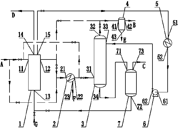
[0021] Ammonia separation device designed by the present invention (abbreviation device, see figure 1 , figure 2 , in the figure, the solid arrow line is the device connection structure in the production stage, and the dotted arrow line is the device connection structure in the production preparation stage), which is characterized in that the device mainly includes a heat exchange evaporator 1, a gas cooler 2, and an absorption tower 3 , gas-liquid separator 4, absorbent cooler 5, high-pressure pump 6 and flash evaporator 7, as well as connecting pipelines and two sets of process switching valves.

[0022] The heat exchange evaporator 1 of the device of the present invention is designed with five process nozzles, which are respectively a hot flow inlet 11, a hot flow outlet 12, a cold flow inlet 13, a cold flow gas phase outlet 14 and a cold flow liquid phas...


PUM


Abstract

The invention discloses an ammonia separation device and method. The ammonia separation device comprises a heat exchange evaporator, a gas cooler, an absorption tower, a gas-liquid separator, an absorbent cooler, a high-pressure pump, a flash evaporator, a connection pipe and two process switching valves. In a catalyst heating and reducing stage, gas from the tower sequentially passes through the gas cooler, the heat exchange evaporator and the gas-liquid separator and returns a system to recycle after being separated from an ammonia water mixture; in a production stage, gas from the tower sequentially passes through the heat exchange evaporator, the gas cooler, the absorption tower and the gas-liquid separator and then is recycled after so ammonia products are seperated, and the absorbent sequentially passes through the absorption tower, the flash evaporator, the heat exchange evaporator, the absorbent cooler and the high-pressure pump so as to finish absorption and ammonia desorption processes and then is recycled; and all devices are connected and switched through pipes and the process switching valves. Compared with the condensed ammonia separation, the ammonia separation device and method disclosed by the invention can realize respective recycle of recycle gas and the absorbent and high-efficiency separation of products and str remarkable in energy-saving and consumption-reducing effects.

Description

technical field [0001] The invention relates to a fertilizer production device, in particular to an ammonia separation device and method. The device and its method are especially suitable for ammonia separation and production of synthetic ammonia. Background technique [0002] In the classic ammonia synthesis separation system, a certain proportion of hydrogen and nitrogen mixed gas reacts in the ammonia synthesis tower to form a mixed gas with a certain concentration of ammonia (mainly hydrogen, nitrogen, ammonia and a small amount of inert gas, which is called the outlet of the tower here. Gas), the ammonia content is generally 10~20% (v). In order to recycle most of the unreacted hydrogen and nitrogen mixed gas, it is necessary to separate the ammonia in the reacted mixed gas as an ammonia product, and the remaining hydrogen and nitrogen mixed gas (called cycle gas) is returned to the synthesis tower for recycling. At present, the ammonia separation device used in the i...

Claims


Application Information

Patent Timeline
Patent Type & Authority Patents(China)
IPC IPC(8): C01C1/12
CPCY02P20/10
Inventor 杜佩衡李蓓孙土金杜剑婷郑献军张继军姚红果陈学青董强富
Owner TIANJIN HENGCHUANG MODERN TOWER TECH
Why Eureka
Try Eureka