
Roof-type unfolding locking device of aircraft

A technology for aerospace vehicles and locking devices, which is applied to aerospace vehicles, aircraft, aerospace equipment, etc., and can solve problems such as increased antenna weight, reduced reliability of deployment mechanisms, and increased mechanism weight

Active Publication Date: 2013-02-13
SHANGHAI AEROSPACE SYST ENG INST
View PDF5 Cites 13 Cited by
  • Summary
  • Abstract
  • Description
  • Claims
  • Application Information

AI Technical Summary

Problems solved by technology

[0004] (2) The bending stiffness of the antenna is improved by strengthening the design of the antenna structure, but it also brings about a substantial increase in the weight of the antenna;
[0005] (3) Adding constraint points in the cantilever area of ​​the antenna also reduces the reliability of the deployment mechanism while increasing the weight of the mechanism

Method used


Image

  • Roof-type unfolding locking device of aircraft
  • Roof-type unfolding locking device of aircraft

Examples


Embodiment Construction

[0026] The invention will be described in more detail hereinafter with reference to the accompanying drawings showing embodiments of the invention. However, this invention may be embodied in many different forms and should not be construed as limited to the embodiments set forth herein. Rather, these embodiments are provided so that this disclosure will be thorough and complete, and will fully convey the scope of the invention to those skilled in the art. In these drawings, the size and relative sizes of layers and regions may be exaggerated for clarity.

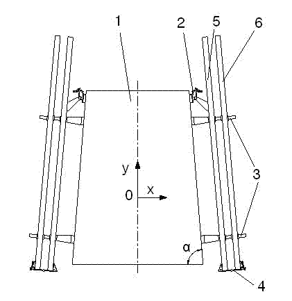
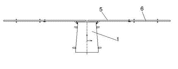
[0027] now refer to Figure 1-2 The roof-type deployment locking device of an aerospace vehicle according to an embodiment of the present invention will be described in detail. Said device comprises a spacecraft platform 1, driving locking device 2, compression releasing device 3, driving hinge 4 and at least two pairs of planar antenna inner boards 5 and planar antenna outer boards 6, said planar antenna inner board 5 and...


PUM


Abstract

The invention provides a roof-type unfolding locking device of an aircraft. The roof-type unfolding locking device comprises an aircraft platform, a driving locking device, a compressing and releasing device, a driving hinge and at least two pairs of inner planar antenna plates and outer planar antenna plates, wherein at the closing-up state, the inner planar antenna plates and the outer planar antenna plates are arranged at two sides of the aircraft platform in a roof layout and are fixed by the compressing and releasing device; and at the unfolded state, the inner planar antenna plates and the outer planar antenna plates are driven to be unfolded through the driving locking device and the driving hinge. Compared with the prior art, the roof-type unfolding locking device of the aircraft sufficiently utilizes the aircraft platform as an installation fixing plane of a planar antenna, the length of the cantilever arm of the antenna is reduced, and the problem that the fundamental frequency of the antenna is too low due to the fact that the cantilever arm is too long while the planar antenna is closed up is effectively solved; and meanwhile the roof-type unfolding locking device has the functions of fastening, unfolding and locking of one, two and more than two antennaes.

Description

technical field [0001] The invention relates to the technical field of an aerospace vehicle planar antenna deployment mechanism, in particular to a roof-type deployment locking device for an aerospace vehicle. technical background [0002] According to the electrical performance and imaging quality and accuracy requirements of planar phased array antennas, the "H" configuration is often used when the spacecraft platform is folded. For planar antennas, this configuration makes the antenna a cantilever beam state, it cannot be fixed with the spacecraft platform, and the way the antenna is stressed is bad. In order to solve the problem that the fundamental frequency of the planar antenna is too low when the plane antenna is folded, most of the domestic and foreign aerospace vehicles currently use the following methods: [0003] (1) Compress the width between the antenna mounting surfaces on both sides of the rectangular platform of the spacecraft as much as possible to ensure ...

Claims


Application Information

Patent Timeline
IPC IPC(8): B64G1/66H01Q1/08
Inventor 李波周鑫
Owner SHANGHAI AEROSPACE SYST ENG INST
Learn More