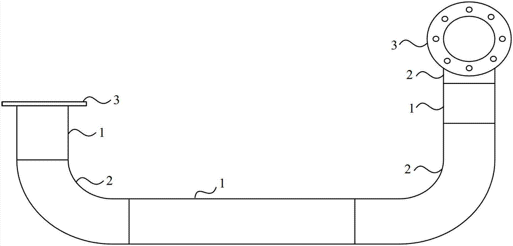
Welding method of variable manifold for locomotive
A welding method and technology of connecting pipes, applied in welding medium, welding equipment, welding equipment and other directions, can solve the problems of poor flange sealing effect, large flange deformation, long heating time, etc., to reduce the risk of leakage, Avoid the influence of the sealing effect, the effect of short operation time
- Summary
- Abstract
- Description
- Claims
- Application Information
AI Technical Summary
Problems solved by technology
Method used
Image

Examples
Embodiment Construction
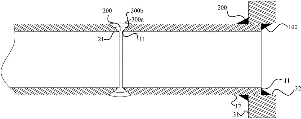
[0026] Embodiment 1 of the present invention first aims at the problem of deformation of the flange caused by the corner joint TIG welding of the pipe and the flange in the prior art, and the connection between the end of the pipe inserted into the flange part on the variable joint pipe and the inner wall of the flange place, such as figure 2 The welding method of the first corner joint 100' shown is improved, and the first corner joint 100 is welded by a first gas shielded welding method, and the first gas shielded welding method uses a solid welding wire and an argon-rich gas.
[0027] Specifically, the welding material of the first gas-shielded welding method can be selected according to the following examples: the welding wire is, for example, a solid welding wire with a grade of ER50-6, and the shielding gas is, for example, made of 80% argon Ar and 20% carbon dioxide CO 2 The formed gas, the welding torch can adopt the welding torch with wire feeding tube, and welding w...
PUM
| Property | Measurement | Unit |
|---|---|---|
| diameter | aaaaa | aaaaa |
| length | aaaaa | aaaaa |
| diameter | aaaaa | aaaaa |
Abstract
Description
Claims
Application Information
 - Generate Ideas
- Intellectual Property
- Life Sciences
- Materials
- Tech Scout
- Unparalleled Data Quality
- Higher Quality Content
- 60% Fewer Hallucinations
Browse by: Latest US Patents, China's latest patents, Technical Efficacy Thesaurus, Application Domain, Technology Topic, Popular Technical Reports.
© 2025 PatSnap. All rights reserved.Legal|Privacy policy|Modern Slavery Act Transparency Statement|Sitemap|About US| Contact US: help@patsnap.com