
Continuous dispensing system and continuous dispensing method

A technology of dispensing and gluing, applied in the direction of coating, device for coating liquid on the surface, etc., can solve the problems of manual peeling, low pass rate, easy inhalation space, etc., so as to reduce production cost and improve product pass rate. , the effect of improving production efficiency

Inactive Publication Date: 2015-09-09
林英志
View PDF5 Cites 0 Cited by
  • Summary
  • Abstract
  • Description
  • Claims
  • Application Information

AI Technical Summary

Problems solved by technology

But this kind of continuous glue dispensing system generally has air bubbles. In the photoelectric field with high requirements (such as liquid crystal screen), it is necessary to degas the glue, while the degassing process such as centrifugal stirring in the prior art can only remove the glue. Bubbles contained in the glue, but there are molecular-level gases dissolved in the glue, which cannot be removed by the existing technology. These gases will be precipitated under the influence of pressure and other conditions during dispensing, causing bubbles to appear in the LCD screen, which needs to be manually stripped and re-applied. Bonding, there are problems such as high rework rate and low pass rate
These technical problems lead to high prices of products such as capacitive touch screens, which limit the promotion and application of products
[0003] In addition, the existing dispensing system generally has glue overflow during use. In order to solve the problem of glue overflow, a method in the prior art is to generate negative pressure in the dispensing cylinder after a product is produced, so as to Make the glue at the end of the dispensing needle suck back a little, but this technology requires precise control of the amount of suck back, and a slight error will easily suck into the space, resulting in air bubbles and affecting the production pass rate

Method used


Image

  • Continuous dispensing system and continuous dispensing method
  • Continuous dispensing system and continuous dispensing method
  • Continuous dispensing system and continuous dispensing method

Examples


Embodiment Construction

[0027] The present invention will be further described below in conjunction with the accompanying drawings and specific embodiments, so that those skilled in the art can better understand the present invention and implement it, but the examples given are not intended to limit the present invention.

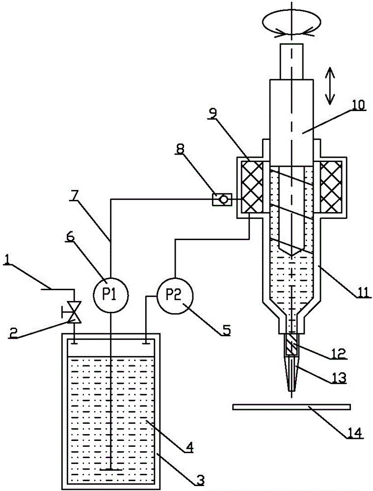
[0028] Such as figure 1 As shown, the continuous dispensing system of the present invention comprises a dispensing pump body 11, a dispensing needle 13 is provided at the lower end of the dispensing pump body 11, a plunger 10 is arranged in the dispensing pump body 11, and a dispensing pump body 11 top is provided with a Gas separator 9 is arranged, and gas separator 9 is provided with viscose inlet; The bottom of the container 3, the pipeline between the rubber pump 6 and the gas separator 9 is provided with a one-way valve 8; the upper part of the container 3 is connected to the vacuum pump 5; 1 is provided with a shut-off valve 2 .

[0029] When working, the upper part of the...


PUM


Abstract

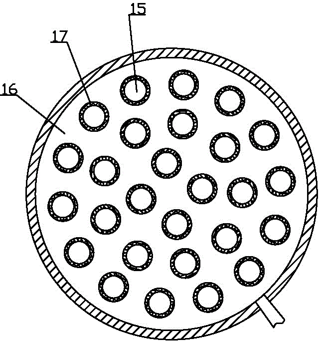
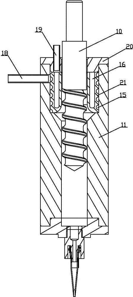
The invention discloses a continuous glue dispensing system comprising a glue dispensing pump body; a glue dispensing needle is disposed at the lower end of the glue dispensing pump body; a plunger is disposed in the glue dispensing pump body; a gas separator is disposed at the upper part of the glue dispensing pump body; a glue inlet is disposed on the gas separator; the gas separator comprises a first channel and a second channel; the first channel is respectively communicated with the glue inlet and the inner cavity of the glue dispensing pump body; the second channel is communicated with a vacuum pump; the two channels are separated by a diaphragm; the diaphragm is provided with micropores, and the diameter of the micropores is larger than the diameter of air molecules and smaller than the diameter of the glue molecules. According to the invention, the glue is treated by degasification twice; molecular-level gas dissolved in the glue is separated by the gas separator, which ensures the purity of the glue entering the glue dispensing pump body; no gas precipitation is caused during the glue dispensing process; continuous glue dispensing is realized while the produced liquid crystal screens are free of bubble; the production efficiency and the product qualified rate are greatly improved; and the production cost of the products is reduced.

Description

technical field [0001] The invention relates to the field of liquid crystal screen production, in particular to a continuous glue dispensing system and a continuous glue dispensing method used in the production of capacitive touch screens and other liquid crystal screens. Background technique [0002] Capacitive touch screens have been widely used in mobile phones, tablet computers and other fields because of their advantages such as high light transmittance and clarity, accurate positioning, and support for multi-touch. However, during the production process of the capacitive touch screen, in a non-vacuum environment, the traditional dispensing system is generally a plunger type (syringe). Using the thrust to move the plunger forward, the liquid colloid is squeezed and applied to the workpiece. However, this dispensing method cannot realize continuous dispensing production. When one tube of glue is used up, the production needs to be stopped, and the glue needs to be repl...

Claims


Application Information

Patent Timeline
Patent Type & Authority Patents(China)
IPC IPC(8): B05C5/00B05C11/10B05D1/26
Inventor 林英志
Owner 林英志
Learn More