
Coal gasification device for circulating fluidized bed

A circulating fluidized bed and coal gasification technology, which is applied in the gasification of granular/powdered fuels, the manufacture of combustible gas, and the petroleum industry. It can solve complex ash discharge problems and achieve strong controllability and a large operating range.

Inactive Publication Date: 2013-02-06
SOUTHEAST UNIV
View PDF9 Cites 10 Cited by
  • Summary
  • Abstract
  • Description
  • Claims
  • Application Information

AI Technical Summary

Problems solved by technology

At present, there are dozens of coal gasification technologies being applied and developed in the world, and the types of gasification furnaces are also various. According to the state of movement of coal gas and gasification agent in the gasification furnace, it can be divided into moving bed, fluidized bed, There are four types of entrained bed and molten bed gasification methods, and with the development of higher gasification pressure, high-pressure circulating fluidized bed gasifier has become one of the main directions of future development, which is different from normal pressure circulating fluidized bed What is more complex is the ash removal problem faced by high-pressure circulating fluidized bed gasifiers
[0003] At present, the pressurized coal gasification circulating fluidized bed adopts slag discharge at the bottom of the riser, and a large part of the unreacted coal at the bottom of the riser is directly discharged through the slag discharge pipe, and cannot be burned.

Method used


Image

  • Coal gasification device for circulating fluidized bed
  • Coal gasification device for circulating fluidized bed
  • Coal gasification device for circulating fluidized bed

Examples


Embodiment 1

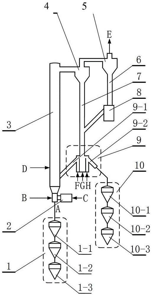
[0022] A method of coal gasification using a pressurized circulating fluidized bed. The gasification medium is introduced into the gasification medium gas inlet B at the bottom end of the riser, and the pulverized coal is added into the riser through the coal inlet D, and the pulverized coal reacts in the riser And rise into the first-stage cyclone separator, the ash and incompletely reacted coke enter the M-type return device through the first-stage cyclone separator and the first-stage feeding pipe, and the ash and unreacted coke that cannot be captured in the first-stage cyclone separator The fully reacted coke passes through the top of the primary cyclone separator and is carried by the gas into the secondary cyclone separator. In the secondary cyclone separator, the ash and incompletely reacted coke that cannot be captured in the primary cyclone separator pass through the secondary cyclone separator. The feeding pipe joins the first-level feeding pipe and enters the M-type...

Embodiment 2

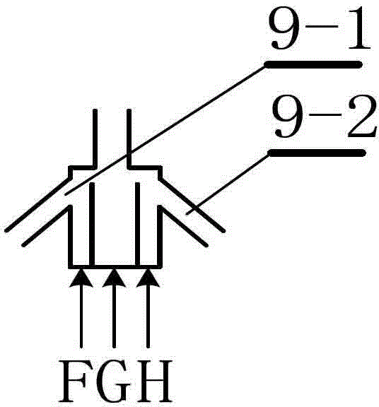
[0024] A device for coal gasification using a pressurized circulating fluidized bed. The pressurized circulating fluidized bed coal gasification device consists of a slag hopper 1, a starting combustion chamber 2, a riser 3, a primary cyclone separator 4, and a secondary cyclone separator 5 , secondary feeding pipe 6, primary feeding pipe 7, U-shaped feeder 8, M-shaped feeder 9, and ash hopper 10, the top of the slag hopper 1 is connected to the bottom of the riser 3, and the lower part of the riser 3 The side is connected with the starting combustion chamber 2, the upper part of the riser 3 is connected with the upper part of the first-stage cyclone separator 4, and the lower part of the first-stage cyclone separator 4 is continuously connected with the top of the M-type feeder 9 through the first-stage feeding pipe 7, and the M-type return Feeder 9, the two sides of M-type feeder 9 are respectively provided with return pipe 9-1 and ash discharge pipe 9-2, and one side of M-ty...

Embodiment 3

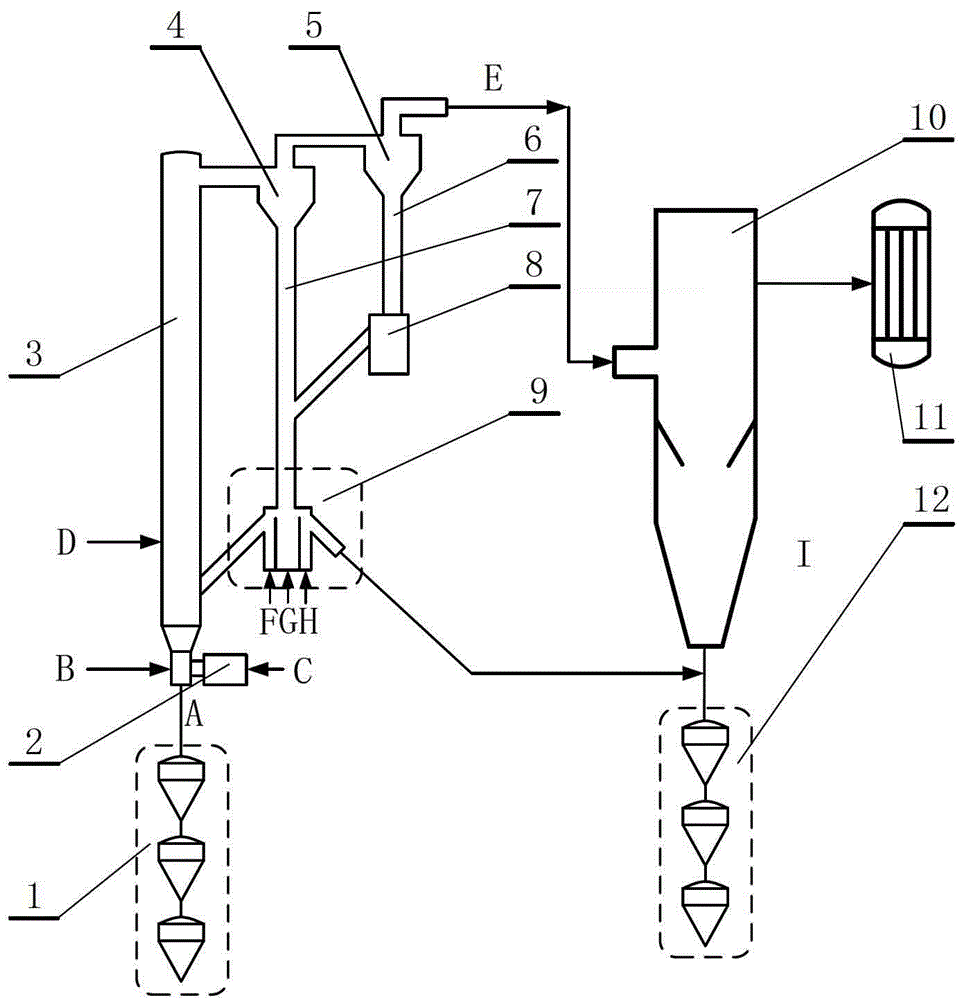
[0026] A pressurized circulating fluidized bed coal gasification method combined with a chiller, the gasification medium is introduced into the gasification medium gas inlet B at the bottom end of the riser 3, and coal slag enters through the slag discharge port A at the bottom end of the riser 3 The slag hopper, the side of the lower part of the riser 3 is connected with the start-up combustion chamber 2, the pulverized coal is added into the riser 3 through the coal inlet D, the pulverized coal reacts in the riser 3 and rises into the first-stage cyclone separator 4, and the ash and incomplete The reacted coke enters the M-type feeder 9 through the first-stage cyclone separator 4 and the first-stage feeding pipe 7, while the ash that cannot be captured in the first-stage cyclone separator 4 and the incompletely reacted coke pass through the first-stage cyclone separator 4. The top of the cyclone separator 4 is entrained by the gas and enters the secondary cyclone separator 5....


PUM


Abstract

The invention discloses a coal gasification device for a circulating fluidized bed. The coal gasification device comprises a start combustion chamber, a raising pipe and a primary cyclone separator, wherein the start combustion chamber is arranged at the lower end of the raising pipe; a slag discharge opening and a fuel inlet are further arranged in the lower end of the raising pipe; a pulverized coal inlet is arranged in the middle part of the raising pipe; a smoke outlet is arranged in the upper end of the raising pipe; the primary cyclone separator is connected with the smoke outlet of the raising pipe; an M-shaped material returner is arranged at the lower end of the primary cyclone separator; a material returning tuyere, a loosening tuyere and an ash discharge tuyere are respectively arranged at the bottom of the M-shaped material returner; a material returning pipe is arranged at the upper end of the material returning tuyere; an ash discharge pipe is arranged at the upper end of the ash discharge tuyere; and the material returning pipe is connected to the middle part of the raising pipe. According to the coal gasification device disclosed by the invention, ash discharge operations are carried out at the bottom of the raising pipe and inside the M-shaped material returner respectively. Compared with the situation of singly discharging slag at the bottom of the raising pipe in the prior art, the M-shaped material returner obviously has a lower carbon content.

Description

technical field [0001] The invention relates to a method and a device for a coal gasification reactor. In particular, it relates to a method and apparatus for a pressurized circulating fluidized bed. Background technique [0002] In today's world, the pollution of the air caused by coal burning is very serious, and clean coal technology must be vigorously developed. Coal gasification is the most important clean coal technology widely used, and the most important unit technology for the development of modern coal chemical industry. At present, there are dozens of coal gasification technologies being applied and developed in the world, and the types of gasification furnaces are also various. According to the state of movement of coal gas and gasification agent in the gasification furnace, they can be divided into moving bed, fluidized bed, There are four types of entrained bed and molten bed gasification methods, and with the development of higher gasification pressure, high-...

Claims


Application Information

Patent Timeline
IPC IPC(8): C10J3/56C10J3/72
Inventor 向文国薛志鹏
Owner SOUTHEAST UNIV
Learn More